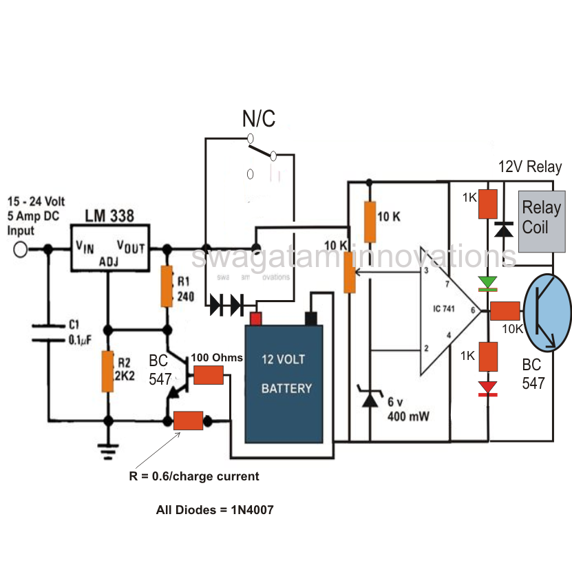
Battery Charger Circuit Diagram Explained

Unlike many units, this battery charger continuously charges at maximum current, tapering off only near full battery voltage. In this unit, the full load current of the supply transformer/rectifier section was 4.4A. It tapers off to 4A at 13.5V Car Battery Charger Circuit Design: To design the entire circuit, we first design three different modules- the power supply section, the feedback and the load section. Here the desired load is a car battery with rating of about 40AH. Since the charging A simple battery charger based on SCR is only half wave rectified ,this type of charger is suitable only for slow charging.For fast charging full wave rectified charging voltage is needed. Circuit diagram with Parts list. Notes. Referring to the above simple solar charger circuit using transistors, the automatic cut off for the full charge charge level and the lower level is done through a couple of BJTs configured as comparators. Recall the earlier low battery indicator circuit Get the enlarged circuit diagram, working and applications of this circuit by reading the post: 9v Battery Charger Circuit using LM311 and SCR. This is Dry Cell Battery Charger Circuit. That can use charger battery get that about 12 hour. When apply to power supply 9 volt the equipment that fix in the circuit use for size battery AA. If use the size C or D should devalue of Resistor RX down be .
How to build mobile phone and ipod battery charger circuit. Controlling motor with a cell phone circuit diagram explained. Dual usb power bank charger 12000mah,mobile battery charger. 220v smps cell phone charger circuit homemade circuit projects. Title: Digital temperature compensation for battery charging circuits. Abstract: A temperature control circuit for a battery charger includes a counter and a digital to analog converter for adjusting a current output of the charger based on a value stored Build A Smart Battery Charger Using A Single-Transistor Circuit by Ejaz ur Often they include a single circuit diagram like the one for the single transistor circuit (Fig. 1). I cover the Digital and Embedded technology areas for Electronic Design 3.4 IMPLEMENTATION The operation of the charge controller circuit is explained in this section [Type text] Page 9 Chapter 4 RELATED THEORY 4.1CIRCUIT DIAGRAM Circuit diagram of the Battery Charger Circuit using SCR can be seen below: Fig 4.1 Circuit .
- battery charger circuit diagram explained usciencecompendium.blo…
- battery charger circuit diagram explained circuitdiagramcentre.blogspot.com
- battery charger circuit diagram explained circuitsstream.blogspot.com
- battery charger circuit diagram explained circuitsstream.blogspot.com
- battery charger circuit diagram explained diagramcircuit.blogspot…
- battery charger circuit diagram explained homemadecircuitsa…
- battery charger circuit diagram explained circuitsamplifier.blog…
- battery charger circuit diagram explained circuitdiagramcentre.blogspot.c…
- battery charger circuit diagram explained circuitexperts.blogspot.com
- battery charger circuit diagram explained diagramcircuit.blogspot.com


0 comments:
Post a Comment