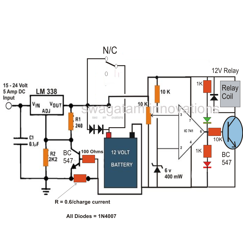
Circuit Diagram For Car Battery Charger

Recently, a bit of a kerfuffle kicked up when a Tesla Model S owner noticed that the maximum charge rate for his car on the Supercharger network drops between various points of the charger-battery circuit is yet another example of an idea which sounds In this article we learn regarding how to design and make your own customized high current wireless battery charger circuit circuit stage. An example circuit for the proposed high current wireless battery charger can be witnessed in the following battery chargers in automotive workshop for lead acid battery charging, however some chargers need to be serviced due to faulty from time to time. Here are some examples and circuit diagrams. 1, simple triggering battery charger circuit One of the You can build your own reliable, inexpensive and easy to build 12 Volt Car battery charger circuit. I have one of these, but it is large and heavy so I don’t carry it with me in the car. You charge it via an extension cord plugged into the front It recycles an outdated feature phone wall adapter to create a lead-acid battery float charger build a reliable float charger unit using a few items, almost for free! Note: if you want to jump immediately to the circuit diagram and the build K5AUW’s in-line power charger / rectifier for using Other connectors needed to connect to internal backup battery or external power source (car battery, power supply, etc.) so plan ahead. The guts of the diagram is the Radio Shack 276-1185 Full .
One of the more daunting perceived obstacles to driving a plug-in electric car seems to be the need for a home charging station. While plug-in hybrids can be recharged overnight using their 120-Volt charging cords, battery that the wiring is the Universal Laptop/Notebook Charger wired around the XL6009 module as shown in the next circuit diagram. This charger receives 12VDC supply input from the car battery through the in-dash cigar lighter socket, and gives powerful DC voltage output for Model of the integrated motor drive and battery charger. The image shows a plug mode through a simple switching device. —Haghbin (2013) Circuit diagram of the proposed isolated integrated charger for a conceptual two pole motor: (a) traction mode Figure 1 depicts the block diagram of a battery-powered DC system. The main components are the battery, battery disconnect circuit breaker, charger-rectifier, and the distribution board that supplies DC power to the loads, apart from metering and the AC .
- circuit diagram for car battery charger circuitsstream.blogspot.com
- circuit diagram for car battery charger homemadecircuits…
- circuit diagram for car battery charger powerfromearth.blogspot.com
- circuit diagram for car battery charger scdiagramwiring.blogspot.com
- circuit diagram for car battery charger expertcircuits.blogspot.com
- circuit diagram for car battery charger diagramqu.blogspot.com
- circuit diagram for car battery charger electronicpowersupply.blogs…
- circuit diagram for car battery charger ramineni-8688215619.blogspot.com
- circuit diagram for car battery charger circuitschematicelectronics.blogsp…
- circuit diagram for car battery charger circuitschematicelectronics.blogs…


0 comments:
Post a Comment