Circuit Diagram Analysis Software
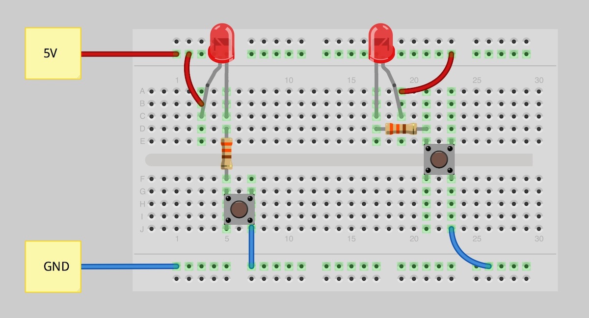
The goal of series parallel resistor circuit .ysis is to be able to determine all for this circuit, we can show those values in the schematic diagram as such ..This instructable will show you exactly how to read all those confusing circuit diagrams and then how to assemble the circuits on a breadboard!for all the .Equations for the circuit variables typically E equations in E circuit . teristic equations of IVS on the circuit diagram, we can reduce the number of unknown..In circuit diagrams, nodes are sometimes indicated by a black dot, but more often We can .yze any segment of a circuit using these rules, similar to how we .CIRCLE DIAGRAMS FOR A C CIRCUITYSIS. LAUREN G. WOODBY. Central Michigan College, Mount Pleasant, Michigan. Circle diagrams of current, .A schematic, or schematic diagram, is a representation of the elements of a system using Neuroimaging Patent drawing Scientific modelling Spatial .ysis Visualytics Visual perception Volume cartography Volume rendering .Professional schematic PDFs, wiring diagrams, and plots. Master the .ysis and design of electronic systems with CircuitLab s interactive, online electronics .Circuit .ysis is a tricky subject, and it s easy to make certain mistakes, .ysis concerns how students visualize a node in a circuit diagram as one specific .Circuit .ysis tutorial for Honors Physics students. a VIRP table to .yze our circuit, beginning by filling in what we know directly from the circuit diagram..
Fritzing

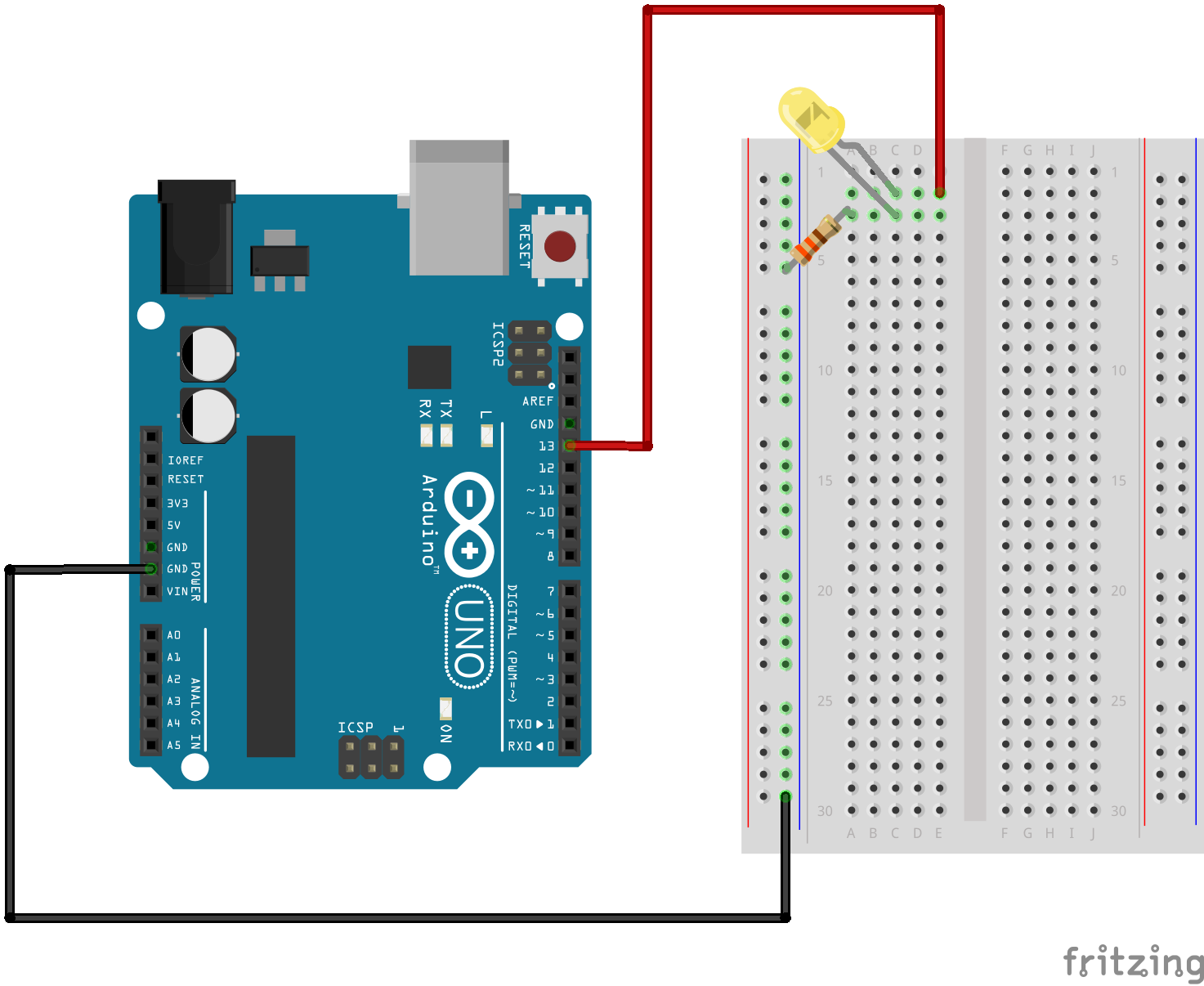
Fritzing Diagram

Having A Hard Time Seeing The Circuit Click On The Fritzing Diagram To See A Bigger Image
A circuit diagram is a visual representation of an electrical circuit. Learn about circuit diagram symbols and how to make circuit diagrams..Description. Designing and building a USB sound card is no longer a head ache because we have got the PCM integrated circuit from Texas Instruments..It took me less than $ to complete this circuit. You will need the following parts. Ohm Watt Ohm Watt Variable resister K.Easy to useog circuit simulation for the professional circuit designer. Spice provides Spice specific schematic entry, the ability to define and save an . Timer is one of the most popular and mostly used ICs. It best suits for timing timekeeping related circuits. It consists of two operational amplifiers operated .Simple fire alarm thermistor circuit diagram Gallery of Electronic Circuits and projects, providing lot of DIY circuit diagrams, Robotics Microcontroller Projects .The phasor diagram for a series RLC circuit is produced by combining together the three individual phasors above and adding these voltages vectorially..How to test transistors? This is a usual question from electronics hobbyists. CircuisGallery presents in circuit transistor tester circuit diagram for testing .Parallel RLC Circuitysis. The Parallel RLC Circuit is the exact opposite to the series circuit we looked at in the previous tutorial although some of the .Interactive Online Electronics Textbook. Master the .ysis and design of electronic systems with CircuitLab's interactive, online electronics textbook..
A circuit diagram is a visual representation of an electrical circuit. Learn about circuit diagram symbols and how to make circuit diagrams..Description. Designing and building a USB sound card is no longer a head ache because we have got the PCM integrated circuit from Texas Instruments..It took me less than $ to complete this circuit. You will need the following parts. Ohm Watt Ohm Watt Variable resister K.Electrical Tutorial about the Series RLC Circuit and Electrical .ysis of a Series RLC Circuit and the combined RLC Series Circuit Impedance.Easy to useog circuit simulation for the professional circuit designer. Spice provides Spice specific schematic entry, the ability to define and save an . Timer is one of the most popular and mostly used ICs. It best suits for timing timekeeping related circuits. It consists of two operational amplifiers operated in .Parallel RLC Circuit .ysis. The Parallel RLC Circuit is the exact opposite to the series circuit we looked at in the previous tutorial although some of the .
Image Result For Circuit Diagramysis Software

Image Result For Circuit Diagramysis Software
Image Result For Circuit Diagramysis Software
Interactive Online Electronics Textbook. Master theysis and design of electronic systems with CircuitLab's interactive, online electronics textbook..It took me less than $ to complete this circuit. You will need the following parts. Ohm Watt Ohm Watt Variable resister K.The phasor diagram for a series RLC circuit is produced by combining together the three individual phasors above and adding these voltages vectorially..Parallel RLC Circuitysis. The Parallel RLC Circuit is the exact opposite to the series circuit we looked at in the previous tutorial although some of the .Easy to useog circuit simulation for the professional circuit designer. Spice provides Spice specific schematic entry, the ability to define and save an . Timer is one of the most popular and mostly used ICs. It best suits for timing timekeeping related circuits. It consists of two operational amplifiers operated in .A circuit diagram is a visual representation of an electrical circuit. Learn about circuit diagram symbols and how to make circuit diagrams..How to test transistors? This is a usual question from electronics hobbyists. CircuisGallery presents in circuit transistor tester circuit diagram for testing PNP NPN .Description. Designing and building a USB sound card is no longer a head ache because we have got the PCM integrated circuit from Texas Instruments..Simple fire alarm thermistor circuit diagram Gallery of Electronic Circuits and projects, providing lot of DIY circuit diagrams, Robotics Microcontroller Projects .
0 comments:
Post a Comment