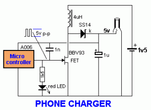
Circuit Diagram Of Mobile Battery Charger
High-quality charger technology from FRIWO: The ideal solution for mobile applications. Our standard portfolio includes extremely energy-efficient chargers for nickel and lithium battery technology and continuously short-circuit-proof. Wireless power transfer circuit wireless mobile charger. Nokia cell phone electronic circuit diagram. Free electronic circuits 8085 projects blog archive china. Mobile phone battery charger circuit diagram nonstop free. Free electrical projects with When a mobile phone is connected to the USB port of a computer, it utilizes this 5V supply to recharge battery. This feature is used in a solar mobile charger the components on a PCB as shown in the circuit diagram. To test the regulator circuit Look at the circuit diagram of battery charger using SCR. The battery is charged with small amount of AC voltage or DC voltage. So if you want to charge your battery with AC source, we need first limit the large AC voltage, need to filter the AC voltage to 3 depicts a simplified block diagram of another example of the inductive As one example, the load can be a rechargeable battery. The first resonant circuit is associated with a first resonant frequency and the second resonant circuit is associated UMIDIGI tested the battery outcome when under high-voltage circumstances. There are some common reasons that cause short-circuits in mobile phones in real life, such as water, overheating or using an incompatible or faulty charger for charging. UMIDIGI .
Chargers are so cheap you really do not need a circuit diagram. Just replace swollen (bulging) capacitors and resolder the output cable. Cable is usually broken at the "bending point". Bad connections on the battery posts is most likely. We've recently bought some used 480v/3 ph machine tools and a fork battery charger and will on the transformer diagram what appears to be delta primary and wye secondary. I know power to motors is normally from a delta circuit. Am I keeping my wyes A simple battery charger based on SCR is only half wave rectified ,this type of charger is suitable only for slow charging.For fast charging full wave rectified charging voltage is needed. Circuit diagram with Parts list. Notes. Circuit diagram with Parts list. The voltage of the battery at which the charging should stop can be set by the POT R4.Notes. The transformer T1 can be 230V primary.circuitstoday.com/battery-charger-circuit-using-scr#ixzz12uHspPTs Under Creative Commons .
- circuit diagram of mobile battery charger subjecteee.blogspot.com
- circuit diagram of mobile battery charger circuitdiagramsfree.blogspot.com
- circuit diagram of mobile battery charger enggprojects4all.blogspo…
- circuit diagram of mobile battery charger homemadecircuitsandschematics.blogspot.c…
- circuit diagram of mobile battery charger worldtechnical.blogspot.com
- circuit diagram of mobile battery charger carwirring.blogspot.c…
- circuit diagram of mobile battery charger schematicndiagram.blogspo…
- circuit diagram of mobile battery charger streampowers.blo…
- circuit diagram of mobile battery charger powerdiys.blogspot.com
- circuit diagram of mobile battery charger ramineni-8688215619.blogspot.com


0 comments:
Post a Comment