Circuit Diagram Potentiometer
Draw the schematic diagram for the circuit to beyzed. Linear taper potentiometers provide a direct, linear relationship between wiper position and .SCHEMATIC DIAGRAM. ILLUSTRATION. INSTRUCTIONS. Begin this experiment with the pencil "lead" circuit. Pencils use a rod made of a graphite clay mixture .A potentiometer is a handy little component often used to control the volume of Sometimes you ll see a potentiometer in a circuit diagram, .A potentiometer is a three terminal resistor with a sliding or rotating contact that forms an The most common way to vary the resistance in a circuit is to use a rheostat. The word . "Linear Type Precision Potentiometer Diagram" PDF ..I m trying to hook up my LCD on a breadboard and a schematic diagram involving a potentiometer is a bit confusing. enter image description .Wire the second terminal to the circuit s output. Terminal is the input of the potentiometer, meaning the output line from the circuit should connect to it..A potentiometer is a useful device, because by just simply adjusting it, it can be used to represent a wide range of resistances in a circuit from anywhere near .However, by only connecting two pins one outside pin and one center pin of a potentiometer to your circuit, you can turn a pot into a variable resistor..

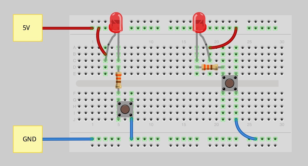
Fritzing Diagram
Fritzing

Descriptionedit
Here is a project of a sound audio level LED meter circuit. It can be used as noise meter, loudness meter, sound pressure or VU level meter and also for variety of .Description. Designing and building a USB sound card is no longer a head ache because we have got the PCM integrated circuit from Texas Instruments..Adjusting the K potentiometer used in the circuit can control the speed of the motor..Simple fire alarm thermistor circuit diagram Gallery of Electronic Circuits and projects, providing lot of DIY circuit diagrams, Robotics Microcontroller Projects .LED dot display based Battery charge level indicator circuit diagram Gallery of Electronic Circuits and projects, providing lot of DIY circuit diagrams, Robotics .Stereo PreAmplifier Circuit Diagram This preamp circuit provides better than dB gain in each channel. PARTS LIST R .This is Bass treble tone control circuit diagram as ideas, we have two circuits both transistors ,ICs op amp as main, so smaller, but high gain signal..Complete circuit symbols of electronic components. All circuit symbols are in standard format and can be used for drawing schematic circuit diagram and layout..Integrated stereo surround sound will come out similar to the Concert Hall. And a simple circuit. Using the LM IC number to expand the difference of the input .Car Battery Charger Circuit Design To design the entire circuit, we first design three different modules the power supply section, the feedback and the load section..

Image Result For Circuit Diagram Potentiometer
Image Result For Circuit Diagram Potentiometer
Image Result For Circuit Diagram Potentiometer

Image Result For Circuit Diagram Potentiometer
Image Result For Circuit Diagram Potentiometer
Image Result For Circuit Diagram Potentiometer
Adjusting the K potentiometer used in the circuit can control the speed of the motor..LED dot display based Battery charge level indicator circuit diagram Gallery of Electronic Circuits and projects, providing lot of DIY circuit diagrams, Robotics .Complete circuit symbols of electronic components. All circuit symbols are in standard format and can be used for drawing schematic circuit diagram and layout..This is Bass treble tone control circuit diagram as ideas, we have two circuits both transistors ,ICs op amp as main, so smaller, but high gain signal..Here is a project of a sound audio level LED meter circuit. It can be used as noise meter, loudness meter, sound pressure or VU level meter and also for variety of .Stereo PreAmplifier Circuit Diagram This preamp circuit provides better than dB gain in each channel. PARTS LIST R .Integrated stereo surround sound will come out similar to the Concert Hall. And a simple circuit. Using the LM IC number to expand the difference of the input .Description. Designing and building a USB sound card is no longer a head ache because we have got the PCM integrated circuit from Texas Instruments..Simple fire alarm thermistor circuit diagram Gallery of Electronic Circuits and projects, providing lot of DIY circuit diagrams, Robotics Microcontroller Projects .Car Battery Charger Circuit Design To design the entire circuit, we first design three different modules the power supply section, the feedback and the load section..
0 comments:
Post a Comment