Circuit Diagram Rf Amplifier
RF circuits are not easy to build. The purpose of this page is to make the circuit diagrams available for educational purposes. I won t be able to help you .Transmitter Circuit Diagram. ASK RF Transmitter. HTE Encoder IC will convert the bit parallel data given to pins D D to serial data and .Remote Control Circuit Through Radio Frequency Without Microcontroller. Description is given below. Appliance Control Block Diagram .Description, working and pin configuration of MHz RF transceiver module. Pin Diagram RF Module Pin Diagram, RF Transmitter and RF Receiver PinOut .A mixer takes an RF input signal at a frequency fRF, mixes it with a LO signal at a frequency . Figure . Anog Multiplier Block Diagram. Figure . .The diagrams, images and screen shots below detail the Audio Amplifier Radio Frequency RF Amplifier Battery Lifetime Output Amplifier A resonant LC or tuned circuit coupled to a large aerial or antenna was used..Hi i now doing project and have to use RF. i want simple RF circuit that use PICf with one input and one output. Please help me.. AJ Pin Functional Identification RF Flow Diagram Diagram Simplified RF Power Discriminator Circuit Diagram . Boltzmann approximation, PET amplifier, circuit diagram, single tone RF power sweepysis, FETs, device libraries, .
Fritzing

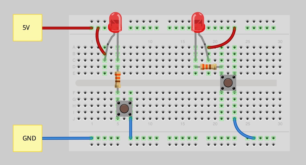
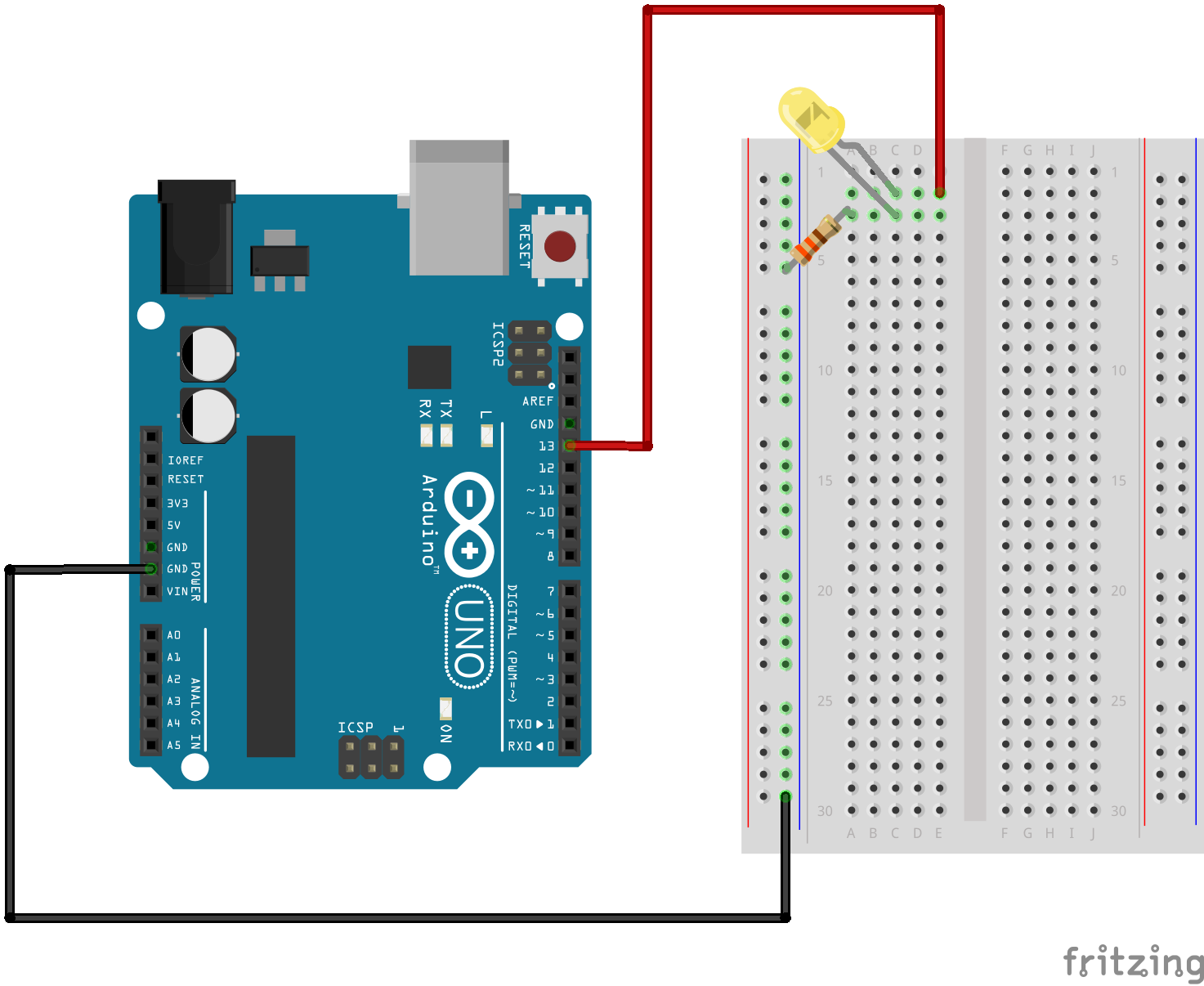
Fritzing Diagram

Having A Hard Time Seeing The Circuit Click On The Fritzing Diagram To See A Bigger Image
Free electronics DIY projects with circuit diagram and description with each project. All projects are divided into different categories..Remote Control Circuit Through Radio Frequency Without Microcontroller Description This is a simple type remote control by using RF communication without microcontroller..This simple LED driver circuit can be used to drive many types of high power LEDs of different watts. The circuit is using LMT voltage regulator..Description. The IR to RF transmitter circuit given here can convert the IR signals from your remote to RF signals to long distances. The circuit given here is a good .Radio frequency RF circuit diagrams also see RF Amplifier and Transmitter circuit diagrams Note that all these links are external and we cannot provide support on .A RF probe is a circuit for testing equipment that converts a high frequency signal into a DC voltage. In this way it is very easy to measure RF voltages f.This is the circuit diagram of W power amplifier which built using power transistors. The circuit above is essentially a mono channel circuit..Two LED CMOS Flasher Circuit Diagram This is a simple led cmos robot flasher, multivibrator circuit using CD six inverter IC. PARTS.LED Knight Rider Running Light Circuit Diagram In this Knight Rider circuit, the is wired as an oscillator. It can be adjusted to give the.Copyright Semtech RF Design Guidelines General PCB Layout Techniques Semtech offers both layer and layer reference designs .

Image Result For Circuit Diagram Rf
Image Result For Circuit Diagram Rf
Image Result For Circuit Diagram Rf
Free electronics DIY projects with circuit diagram and description with each project. All projects are divided into different categories..Radio frequency RF circuit diagrams also see RF Amplifier and Transmitter circuit diagrams Note that all these links are external and we cannot provide support on .Remote Control Circuit Through Radio Frequency Without Microcontroller Description This is a simple type remote control by using RF communication without microcontroller..This simple LED driver circuit can be used to drive many types of high power LEDs of different watts. The circuit is using LMT voltage regulator..Description. The IR to RF transmitter circuit given here can convert the IR signals from your remote to RF signals to long distances. The circuit given here is a good .A RF probe is a circuit for testing equipment that converts a high frequency signal into a DC voltage. In this way it is very easy to measure RF voltages f.This is the circuit diagram of W power amplifier which built using power transistors. The circuit above is essentially a mono channel circuit..RF radio frequency amplifier circuit schematics also see RF and Transmitter circuit diagrams Note that all these links are external and we cannot provide support .Two LED CMOS Flasher Circuit Diagram This is a simple led cmos robot flasher, multivibrator circuit using CD six inverter IC. PARTS.
Image Result For Circuit Diagram Rf Amplifier
Image Result For Circuit Diagram Rf Amplifier

Image Result For Circuit Diagram Rf Amplifier
LED Knight Rider Running Light Circuit Diagram In this Knight Rider circuit, the is wired as an oscillator. It can be adjusted to give the.This is the circuit diagram of W power amplifier which built using power transistors. The circuit above is essentially a mono channel circuit..Two LED CMOS Flasher Circuit Diagram This is a simple led cmos robot flasher, multivibrator circuit using CD six inverter IC. PARTS.Copyright Semtech RF Design Guidelines General PCB Layout Techniques Semtech offers both layer and layer reference designs .Free electronics DIY projects with circuit diagram and description with each project. All projects are divided into different categories..A RF probe is a circuit for testing equipment that converts a high frequency signal into a DC voltage. In this way it is very easy to measure RF voltages f.Radio frequency RF circuit diagrams also see RF Amplifier and Transmitter circuit diagrams Note that all these links are external and we cannot provide support on .This simple LED driver circuit can be used to drive many types of high power LEDs of different watts. The circuit is using LMT voltage regulator..Remote Control Circuit Through Radio Frequency Without Microcontroller Description This is a simple type remote control by using RF communication without microcontroller..Description. The IR to RF transmitter circuit given here can convert the IR signals from your remote to RF signals to long distances. The circuit given here is a good .
0 comments:
Post a Comment