Circuit Diagram Thermistor
In this article, we go over how to build simple thermistor circuits. There are main types of thermistors negative temperature coefficient NTC thermistors and positive temperature coefficient PTC thermistors. NTC thermistors are thermistors whose resistance decreases when the .Thermistors have either a negative temperature coefficient NTC or a positive You can use PTC thermistors, or posistors, as current limiting devices for circuit protection Two , Three , and Four Wire Connection Diagrams..Browse through a total of Thermistor Projects and Circuits. This simple temperature relay circuit can be used to signal a fire or setpoint for temperature .This application note focuses on circuit solutions that use Negative Temperature Coefficient NTC ther mistors in the design. The Thermistor .This project covers a simple fire alarm circuit using thermistor and timer IC. Here thermistor is used as a fire detector. Thermistor is temperature sensitive .Circuit Diagram of Thermistor Temperature Sensing Alarm Temerature Sensor Circuit Diagram. The element in the circuit that senses the .Have you ever wondered how some devices like thermostats, D printer heat beds, car engines, or ovens measure temperature? With this .Thermistor is a variable resistance type of transducer thermistor working principle is Simple Fire Alarm Circuit Diagram Using Thermistor..Using a thermistor in the position shown makes a heat activated sensor. A change in temperature will alter the output of the opamp and energize the relay and .
Fritzing

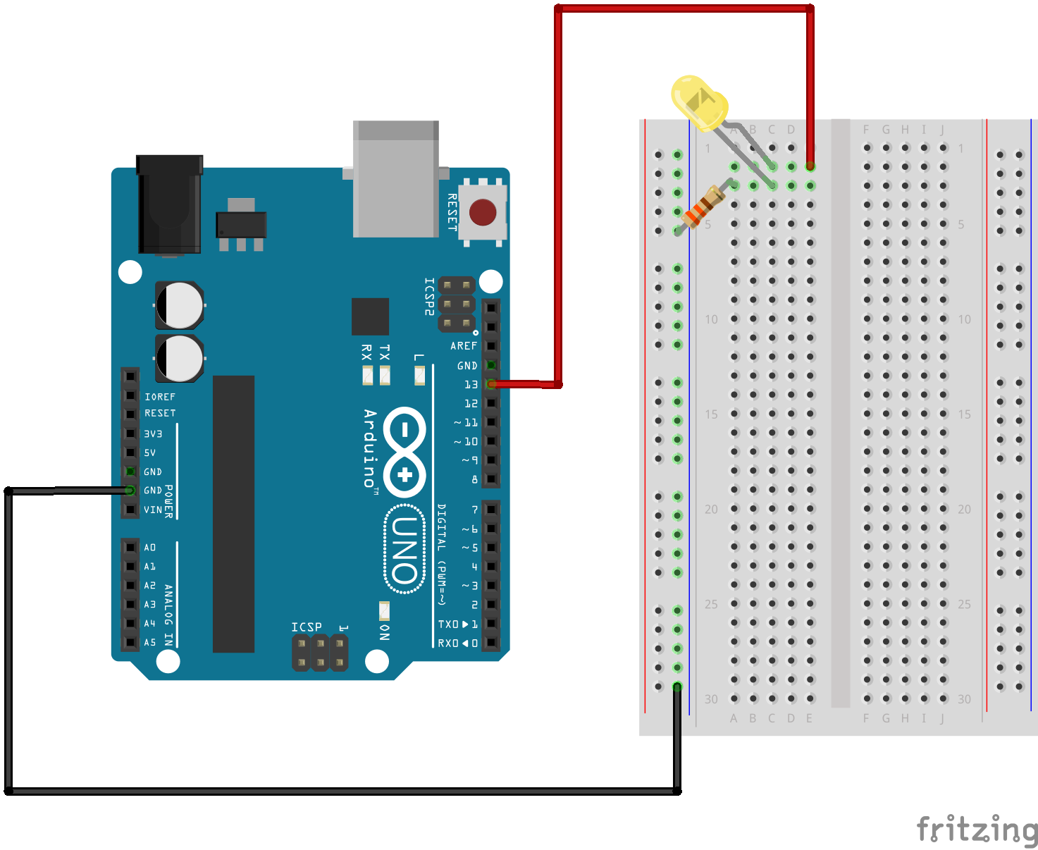
Fritzing Diagram

Having A Hard Time Seeing The Circuit Click On The Fritzing Diagram To See A Bigger Image
Simple fire alarm thermistor circuit diagram Gallery of Electronic Circuits and projects, providing lot of DIY circuit diagrams, Robotics Microcontroller Projects .A Thermistor is used in the circuit for sensing the heat and two K variable resistors are used to adjust the circuit to activate the relay on the desired temperature..This is a circuit named thermistor temperature sensing alarm, in which the alarm raises whenever the temperature crosses a certain limit..The circuit diagram and details of a Fire Alarm Circuit Using IC and Thermistor is explained in this post..Complete circuit symbols of electronic components. All circuit symbols are in standard format and can be used for drawing schematic circuit diagram and layout..Most simple FM transmitter circuit diagram Gallery of Electronic Circuits and projects, providing lot of DIY circuit diagrams, Robotics Microcontroller Projects .Here is a simple circuit which can be used as a heat sensor. In the following circuit diagram thermistor and Ohms resistance is connected in series and makes a .This panic button alarm circuit is designed using timer IC in astable mode. It helps us to intimate others about our bad situation without any delay..A basic led circuit is nothing more than simple things which are a battery, a current limiting resistor and an LED. A current limiting resistor is used to provide .Measuring elays CM Range Description The thermistor motor protection relays CM MSE, CM MSS and CM MSN are used to control motors equipped with PTC .
Image Result For Circuit Diagram Thermistor
Image Result For Circuit Diagram Thermistor
Image Result For Circuit Diagram Thermistor
Simple fire alarm thermistor circuit diagram Gallery of Electronic Circuits and projects, providing lot of DIY circuit diagrams, Robotics Microcontroller Projects .A Thermistor is used in the circuit for sensing the heat and two K variable resistors are used to adjust the circuit to activate the relay on the desired temperature..This is a circuit named thermistor temperature sensing alarm, in which the alarm raises whenever the temperature crosses a certain limit..The circuit diagram and details of a Fire Alarm Circuit Using IC and Thermistor is explained in this post..Complete circuit symbols of electronic components. All circuit symbols are in standard format and can be used for drawing schematic circuit diagram and layout..Most simple FM transmitter circuit diagram Gallery of Electronic Circuits and projects, providing lot of DIY circuit diagrams, Robotics Microcontroller Projects .Here is a simple circuit which can be used as a heat sensor. In the following circuit diagram thermistor and Ohms resistance is connected in series and makes a .
Image Result For Circuit Diagram Thermistor
Image Result For Circuit Diagram Thermistor
Image Result For Circuit Diagram Thermistor
The circuit diagram and details of a Fire Alarm Circuit Using IC and Thermistor is explained in this post..Complete circuit symbols of electronic components. All circuit symbols are in standard format and can be used for drawing schematic circuit diagram and layout..A Thermistor is used in the circuit for sensing the heat and two K variable resistors are used to adjust the circuit to activate the relay on the desired temperature..Most simple FM transmitter circuit diagram Gallery of Electronic Circuits and projects, providing lot of DIY circuit diagrams, Robotics Microcontroller Projects .Simple fire alarm thermistor circuit diagram Gallery of Electronic Circuits and projects, providing lot of DIY circuit diagrams, Robotics Microcontroller Projects .Measuring elays CM Range Description The thermistor motor protection relays CM MSE, CM MSS and CM MSN are used to control motors equipped with PTC temperature .A basic led circuit is nothing more than simple things which are a battery, a current limiting resistor and an LED. A current limiting resistor is used to provide .Here is a simple circuit which can be used as a heat sensor. In the following circuit diagram thermistor and Ohms resistance is connected in series and makes a .This is a circuit named thermistor temperature sensing alarm, in which the alarm raises whenever the temperature crosses a certain limit..This panic button alarm circuit is designed using timer IC in astable mode. It helps us to intimate others about our bad situation without any delay..
0 comments:
Post a Comment