Circuit Diagram Variable Resistor
Variable Voltage Power Supply Circuit using the LMT voltage regulator to The LMT is an adjustable terminal positive voltage regulator capable of regulator from zero and ends up to volt? justify with design circuit diagram??.This regulator is v variable power supply circuit,A that adjust output voltage V to Figure The circuit diagram of V A Variable DC power supply..But this circuit can be created with a single IC is LM The LM or LM series of adjustable terminal positive voltage regulators is capable of supplying .A project about adjustable regulated power supply circuit using xx IC..Variable DC Supply. A Variable DC Power Supply is very important for electronics The working of the circuit is as follows..Useful for electronics hobbyists, this linear workbench desktop power supply circuit converts a high input voltage V from [ ] .Block Diagram of Power Supply. Here, we have got an input high The most important part of this circuit is the variable voltage regulator..This is a high quality power supply with a continuously variable stabilised output Make sure that you follow the circuit diagram very care fully for these .The LM circuit is shown in the below figure is a typical configuration of the LM voltage regulator circuit diagram including the decoupling capacitors..
Fritzing

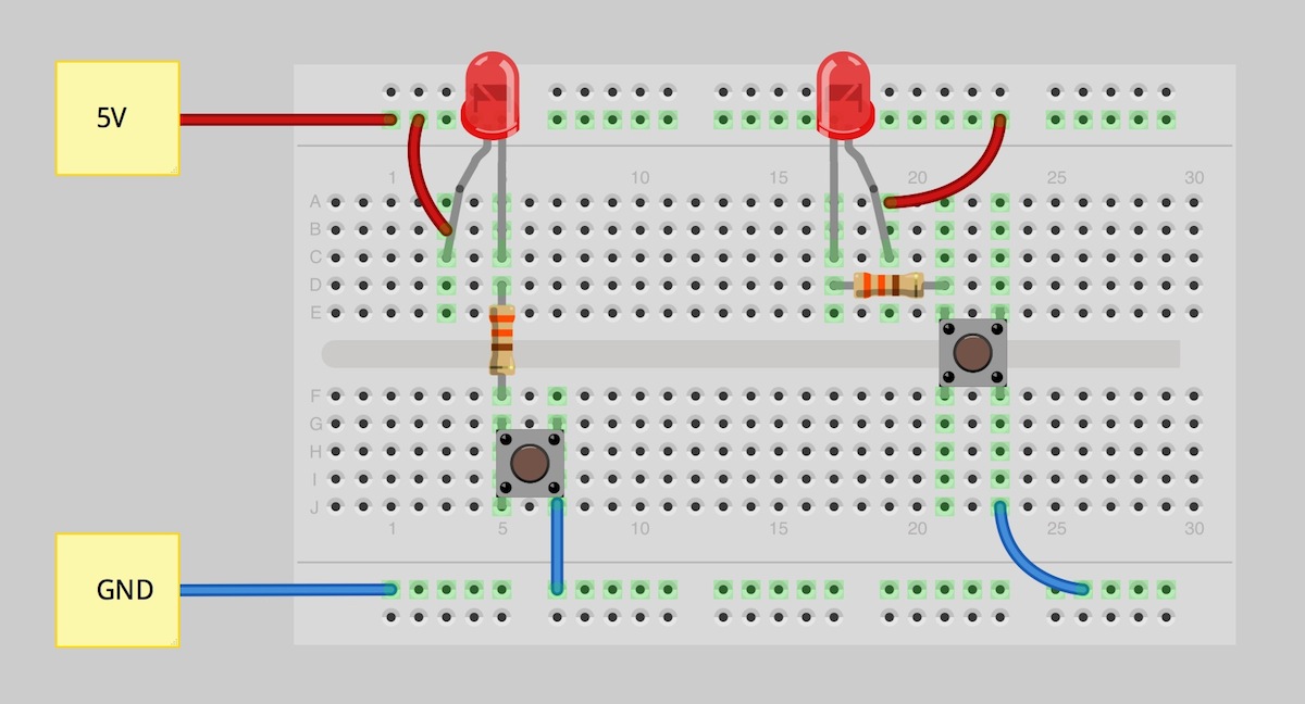
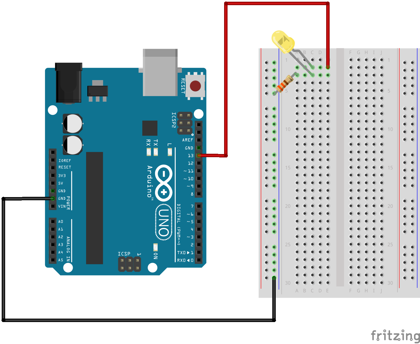
Fritzing Diagram

Having A Hard Time Seeing The Circuit Click On The Fritzing Diagram To See A Bigger Image
CircuitDiagram.Net provides huge collection of electronic circuit design alarm, amplifier, digital circuit, power supply, inverter, radio, robot and more.Electronic circuit diagram database. The most popular circuit diagrams such as amplifier, fm transmitter, power supply and other. Electronics projects. n .Free electronics DIY projects with circuit diagram and description with each project. All projects are divided into different categories..Schematic and description of a dark detecting circuit. This dark activated circuit will switch on any equipment when it will detect no light..It took me less than $ to complete this circuit. You will need the following parts. Ohm Watt Ohm Watt Variable resister K.This is Bass treble tone control circuit diagram as ideas, we have two circuits both transistors ,ICs op amp as main, so smaller, but high gain signal..Most simple FM transmitter circuit diagram Gallery of Electronic Circuits and projects, providing lot of DIY circuit diagrams, Robotics Microcontroller Projects .Simple fire alarm thermistor circuit diagram Gallery of Electronic Circuits and projects, providing lot of DIY circuit diagrams, Robotics Microcontroller Projects .This regulator is v variable power supply circuit,A that adjust output voltage V to volts, and important is the overcurrent protection at A..A simple am transmitter circuit with diagram and schematic. This am radio transmitter can transmit audio sound to your backyard. Follows FCC regulations and still .
Image Result For Circuit Diagram Variable Resistor
Image Result For Circuit Diagram Variable Resistor

Image Result For Circuit Diagram Variable Resistor
How does the circuit of a basic Variable speed electric variable speed circuit work. is the wiring diagram correct it doesnt show a variable resistor .The is a variable voltage regulator with adjustable terminal positive voltage pins designed to supply more than . A of load current..Related circuit diagram variable regulated power supply free ebooks honda civic manual drawing closer the paintings and personal reflections of.Understanding VFD circuit then it's better to understand what is the variable frequency drive circuit Following Fig. diagram shows an electronic diagram of .Variable Power Supplies Projects and Circuits This simple variable power supply circuit has a low production cost and delivers an output voltage between , .A project about adjustable regulated power supply circuit using xx IC.VFD Fundamentals Copyright Kilowatt Classroom, Heat Sink on Module Back Plane Module Schematic Diagram Variable Toyze the circuit assume a .Design Strategy for a Phase Variable Frequency Drive VFD By Omar David Munoz Senior Project ELECTRICAL ENGINEERING DEPARTMENT California Polytechnic State University.Night. Circuit diagram and working of variable voltage power supply from fixed voltage regulator. Voltage regulator is used to get fixed voltage at the output.. speed and capacity control called a variable Variable Frequency Drives And AC Motor Speed. A circuit diagram of a three phase VFD shows that all .
0 comments:
Post a Comment