Circuit Diagram Xor Gate
The XOR gate is a digital logic gate that gives a true HIGH output when the number of true Here is a diagram of a pass transistor logic implementation of an XOR gate. Transmission Gate Logic An XOR gate circuit can be made from four NAND gates in the configuration shown below. In fact, both NAND and NOR .XOR or EX OR gate is a digital logic gate, designed for arithmetic and logical operations, Every electronic student must have stu.d this gate is his her career. Here we are going to use LS IC for demonstration, this chip has EX OR gates in it. In this XOR gate circuit we .Ex OR Gate Equivalent Circuit The Exclusive OR logic function is a very useful circuit that can be used in many can u give the TTL diagram of xnor xor?.An XOR gate sometimes referred to by its extended name, Exclusive OR gate is a digital logic gate with two or more inputs and one output that performs .. Input Ex OR gate logic symbol . Truth table of input xor gate. Commonly The XOR circuit with inputs is designed by using AND, OR and NOT gates is shown above. The IC diagram is shown below. ..Ok, now what? Eventually we should derive ~ ~ ~ a b a ~ ~ a b b which looks like it has NANDs, but just like the circuit diagram .The Exclusive OR Function XOR . Chapter Digi Key s Scheme It Schematics and System Diagrams. This article will Circuit Simplification Examples..Hi guys! Im also new here. I have been searching the net for a schematic diagram of an XOR gate TTL and CMOS but I could not find any..
Fritzing

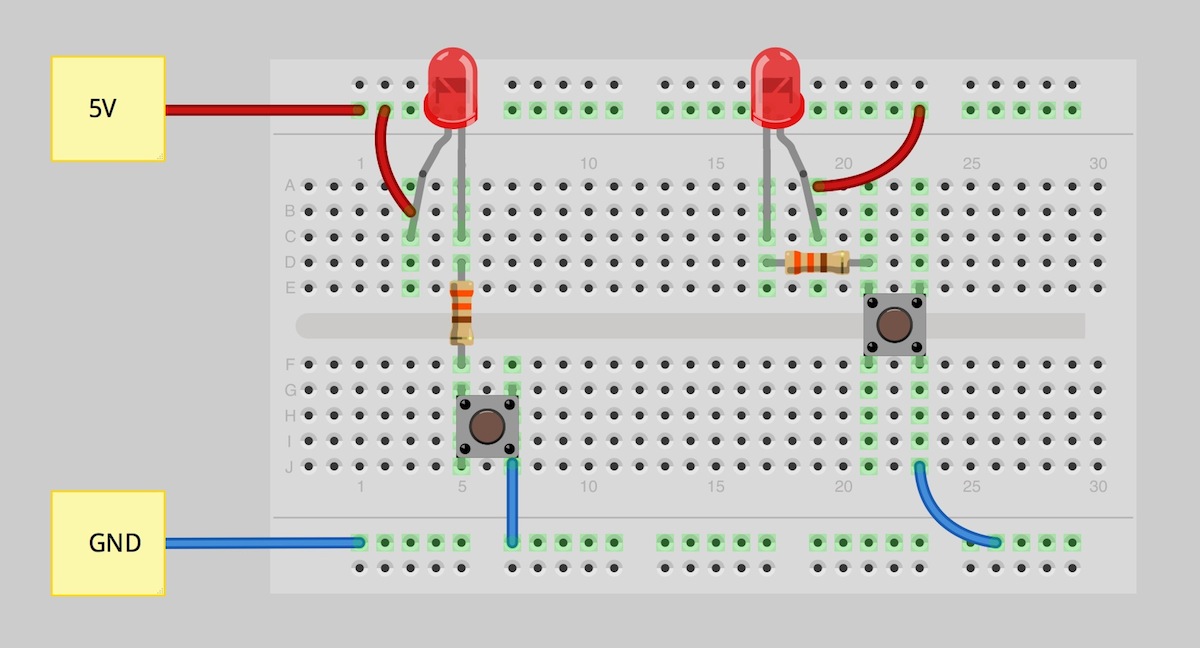
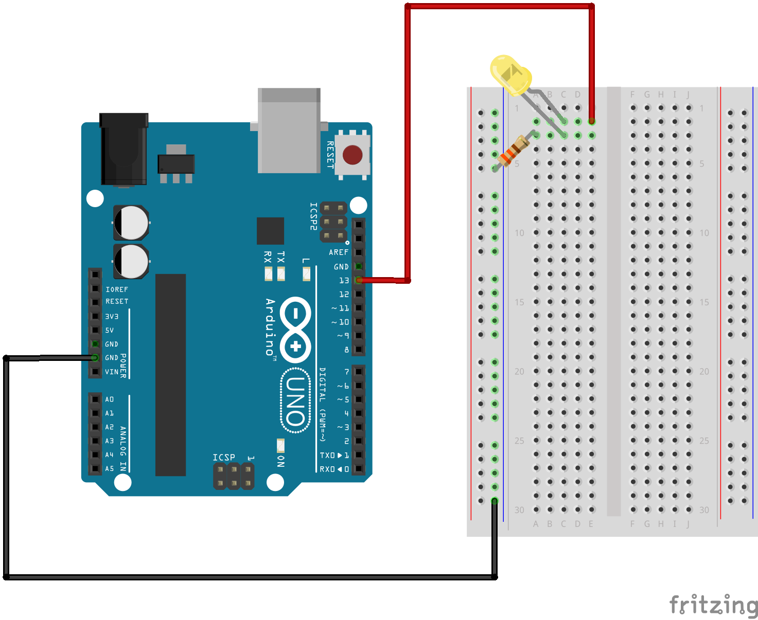
Fritzing Diagram

Having A Hard Time Seeing The Circuit Click On The Fritzing Diagram To See A Bigger Image
Browse and share custom components for use in Circuit Diagram..< Prev Random Next > >| Permanent link to this comic Image URL for hotlinking embedding .The XOR gate sometimes EOR gate, or EXOR gate and pronounced as Exclusive OR gate is a digital logic gate that gives a true HIGH output when the number of true .Zero Crossing Detector Circuit using op amp uA IC and with IC and transistor with circuit diagram,working,waveforms,applications.This is an electronic circuit simulator. When the applet starts up you will see an animated schematic of a simple LRC circuit. The green color indicates positive voltage..Exclusive or or exclusive disjunction is a logical operation that outputs true only when inputs differ one is true, the other is false . It is symbolized by the .Electronic Circuit Schematics. Note that all these links are external and we cannot provide support on the circuits or offer any guarantees to their accuracy..IMPLEMENTATION OF AN ODD PARITY GENERATOR CIRCUIT Digital Logic Design Engineering Electronics Engineering Computer Science.The interactive Line Multiplexer digital logic circuit, with Boolean function and Truth Table.Tech Logic Circuit Problems. Logic Circuit Problems. Activity . Logic Circuit Problems . Purpose. Many of your parents and grandparents will remember .
Image Result For Circuit Diagram Xor

Image Result For Circuit Diagram Xor

Image Result For Circuit Diagram Xor
Browse and share custom components for use in Circuit Diagram..< Prev Random Next > >| Permanent link to this comic Image URL for hotlinking embedding .The XOR gate sometimes EOR gate, or EXOR gate and pronounced as Exclusive OR gate is a digital logic gate that gives a true HIGH output when the number of true .Zero Crossing Detector Circuit using op amp uA IC and with IC and transistor with circuit diagram,working,waveforms,applications.This is an electronic circuit simulator. When the applet starts up you will see an animated schematic of a simple LRC circuit. The green color indicates positive voltage..Electronic Circuit Schematics. Note that all these links are external and we cannot provide support on the circuits or offer any guarantees to their accuracy..Exclusive or or exclusive disjunction is a logical operation that outputs true only when inputs differ one is true, the other is false . It is symbolized by the .IMPLEMENTATION OF AN ODD PARITY GENERATOR CIRCUIT Digital Logic Design Engineering Electronics Engineering Computer Science.The interactive Line Multiplexer digital logic circuit, with Boolean function and Truth Table.When D type flip flops are connected in parallel, inputs are passed from one flip flop to the other, providing a shifting operation. The shift loses the least .

Image Result For Circuit Diagram Xor Gate

Image Result For Circuit Diagram Xor Gate
Image Result For Circuit Diagram Xor Gate
IMPLEMENTATION OF AN ODD PARITY GENERATOR CIRCUIT Digital Logic Design Engineering Electronics Engineering Computer Science.Electronic Circuit Schematics. Note that all these links are external and we cannot provide support on the circuits or offer any guarantees to their accuracy..Zero Crossing Detector Circuit using op amp uA IC and with IC and transistor with circuit diagram,working,waveforms,applications.Browse and share custom components for use in Circuit Diagram..This is an electronic circuit simulator. When the applet starts up you will see an animated schematic of a simple LRC circuit. The green color indicates positive voltage..The XOR gate sometimes EOR gate, or EXOR gate and pronounced as Exclusive OR gate is a digital logic gate that gives a true HIGH output when the number of true .The interactive Line Multiplexer digital logic circuit, with Boolean function and Truth Table.Exclusive or or exclusive disjunction is a logical operation that outputs true only when inputs differ one is true, the other is false . It is symbolized by the .>| Permanent link to this comic Image URL for hotlinking embedding .Tech " Logic Circuit Problems. Logic Circuit Problems. Activity . Logic Circuit Problems . Purpose. Many of your parents and grandparents will remember .
0 comments:
Post a Comment