Circuit Diagram Multiplexer
The multiplexer, shortened to "MUX" or "MPX", is a combinational logic circuit designed to switch one of several input lines through to a single common output line by the application of a control signal..A multiplexer is a circuit that accept many input but give only one output. A demultiplexer function exactly in the reverse of a multiplexer, that is a .It is a combinational circuit with more than one input line, one output line and more The below figure shows the block diagram of a multiplexer .Basic circuit design and multiplexers. . Multiplexer circuit diagram. Here is an implementation of a to multiplexer. Remember that a .Draw the schematic diagram for the digital circuit to beyzed. Explain how these multiplexing techniques work, and what conditions would prompt you to .Multiplexer completely explained design truth table,logical expression,circuit diagram for it..
Fritzing

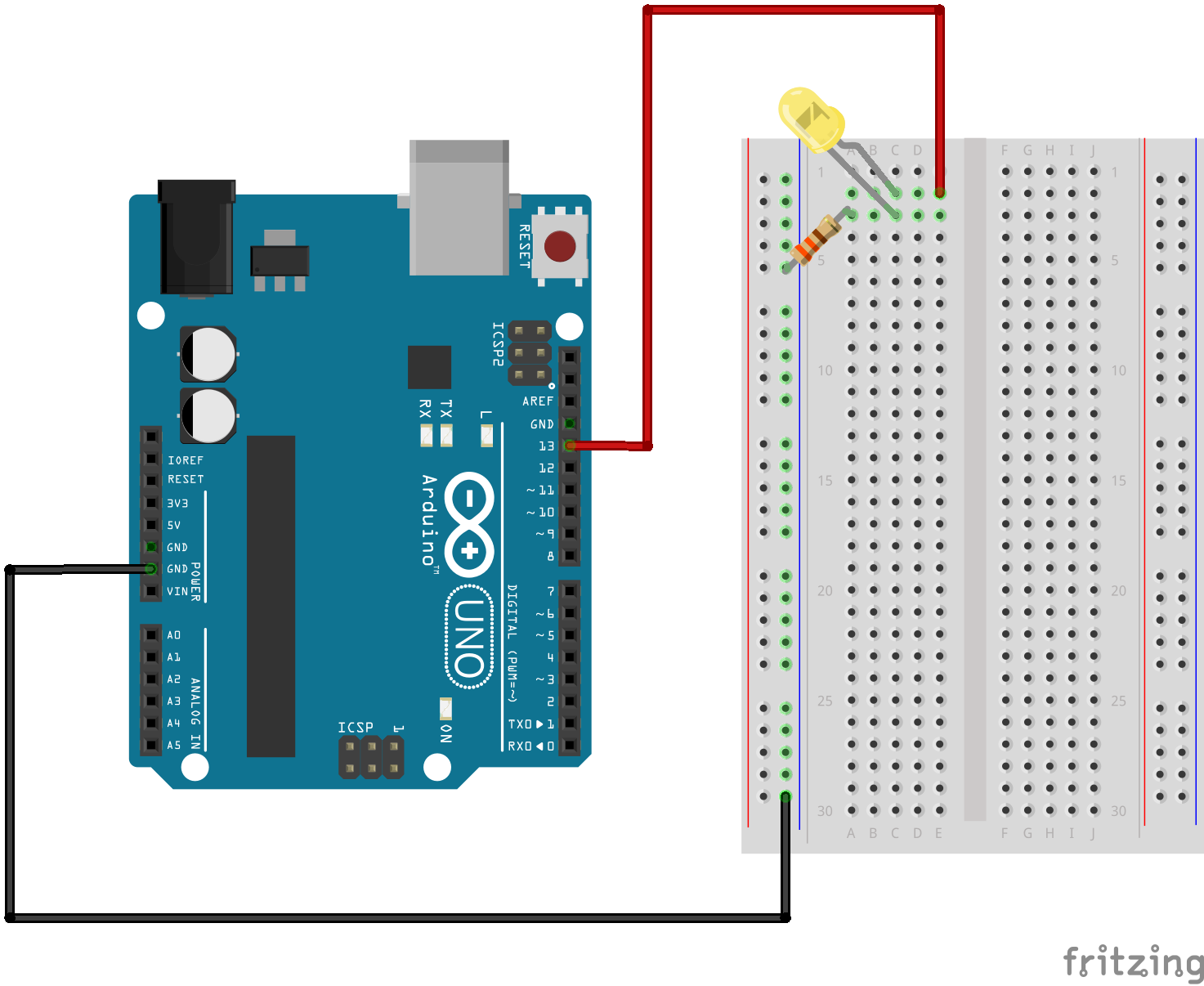
Fritzing Diagram

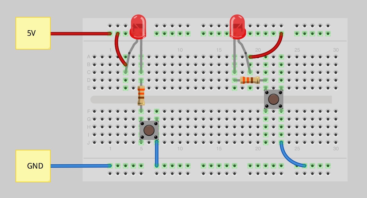
Having A Hard Time Seeing The Circuit Click On The Fritzing Diagram To See A Bigger Image
A multiplexer is a circuit that accept many input but give only one output. A demultiplexer function exactly in the reverse of a multiplexer, that is a demultiplexer .The interactive Line Multiplexer digital logic circuit, with Boolean function and Truth Table.Here is the circuit diagram of display decoder which is used to convert a BCD or binary code into a segment code used to operate a segment LED display..A simple voltmeter circuit with diagram and schematic,made using LM IC and LED Display.This voltmeter circuit indicates voltage from your car battery..Theory . Decoder . In digital electronics, a decoder can take the form of a multiple input, multiple output logic circuit that converts coded inputs into coded .Application Note AN ing and inverting input multiplexers. The outputs of the noninverting and inverting multiplexers are applied to the LTC's AIN and .Electronics Tutorial about the Multiplexer MUX and Digital Multiplexers used in Combinational Logic circuits for the multiplexing of data signals.Fig. The schematic diagram, boolean equation and the truth table of a multiplexer with inputs A and B, select input S and the output Z..The heart of this digital volume controller DVC circuit is channelog multiplexer. Because the k has been connected between every input.Anog multiplexer, a circuit that steers one of the input signals to the output line, is shown in figure. In this circuit each JFET acts as a single pole single .
Image Result For Circuit Diagram Multiplexer

Image Result For Circuit Diagram Multiplexer
Image Result For Circuit Diagram Multiplexer
Image Result For Circuit Diagram Multiplexer

Image Result For Circuit Diagram Multiplexer
Image Result For Circuit Diagram Multiplexer
Basic circuit design and multiplexers Designing circuits The goal in circuit design is to build hardware that solves some problem..Schematic of a to Demultiplexer. Like a multiplexer, it can be equated to a controlled switch. In electronics, a multiplexer or mux is a device that .A multiplexer, abbreviated mux, is a device that has multiple inputs and one output. The schematic symbol for multiplexers is. The truth table for a to multiplexer is.Data Selectors Multiplexers. Learn about data selectors, multiplexers and demultiplexers. basic circuits, multibit MUX and addressing.Theory . Decoder . In digital These types of decoders are combinational circuits that convert binary information from 'n' coded Truth Table of MUX . Fig .Electronics Tutorial about the Multiplexer MUX and Digital Multiplexers used in Combinational Logic circuits for the multiplexing of data signals.Circuit Implementation Using Multiplexers. Theory. The gate implementation of a line to line multiplexer is shown below The circuit symbol for the above .Circuit diagram of multiplexer datasheet, cross reference, circuit and application notes in pdf format..Circuit Description to Multiplexer In general, a multiplexer is a combination of circuits that uses binary information from multiple inputs and directs .A multiplexer is a circuit that accept many input but give only one output. A demultiplexer function exactly in the reverse of a multiplexer, that is a demultiplexer .
0 comments:
Post a Comment