Circuit Diagram Test
What kind of circuit is this? A. Series Circuit. B. Parallel Circuit. C. Complex Circuit. . Below is an example of a parallel circuit. A. True. B. False. Back to top..Physics Electric Circuit Practice Test. For questions , please refer to the circuit below. . What is the total resistance of the circuit? answer. . What is the total .Electric current and voltage Test. Print. . What needs to be done to this circuit so that the lamp lights up? a circuit What is wrong with this circuit diagram?.SCHEMATIC DIAGRAM. ILLUSTRATION. INSTRUCTIONS. This is the simplest complete circuit in this collection of experiments a battery and an incandescent .Powerful online circuit simulator and schematic editor. Professional schematic PDFs, wiring diagrams, and plots. ysis, improving our power supply robustness, and designing and documenting our many test and production fixtures. "..Two technicians are discussing a wire harness construction Technician A says that connector is the male connector because the while plastic connector fits .Use the pull down menus to match the name of the component shown by the circuit symbol. Use the button at the bottom to check your answers..Take the Wiring Schematics Interpretation quick quiz and see if you have technician without a good working knowledge of electric diagrams..Design and build series and parallel circuits, draw labelled diagrams identifying use technological problem solving skills to design, build, and test a device that .DoCircuits Create circuit online, test and measure with real lab equipments and share your design with community. Browse over circuit simulations..
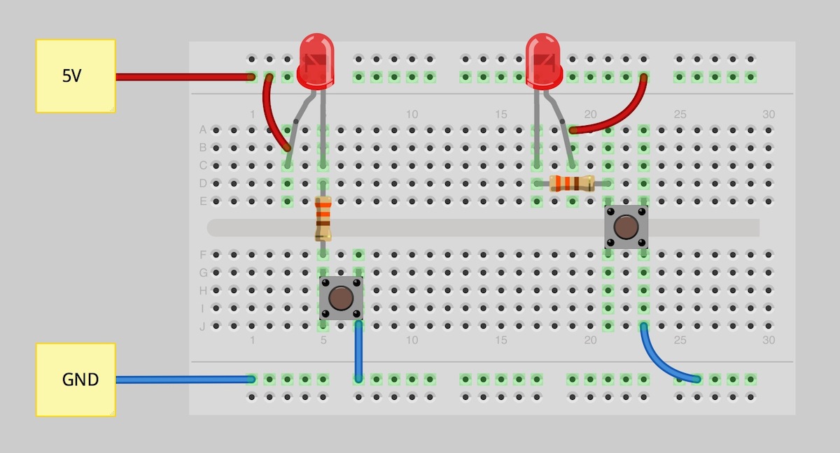
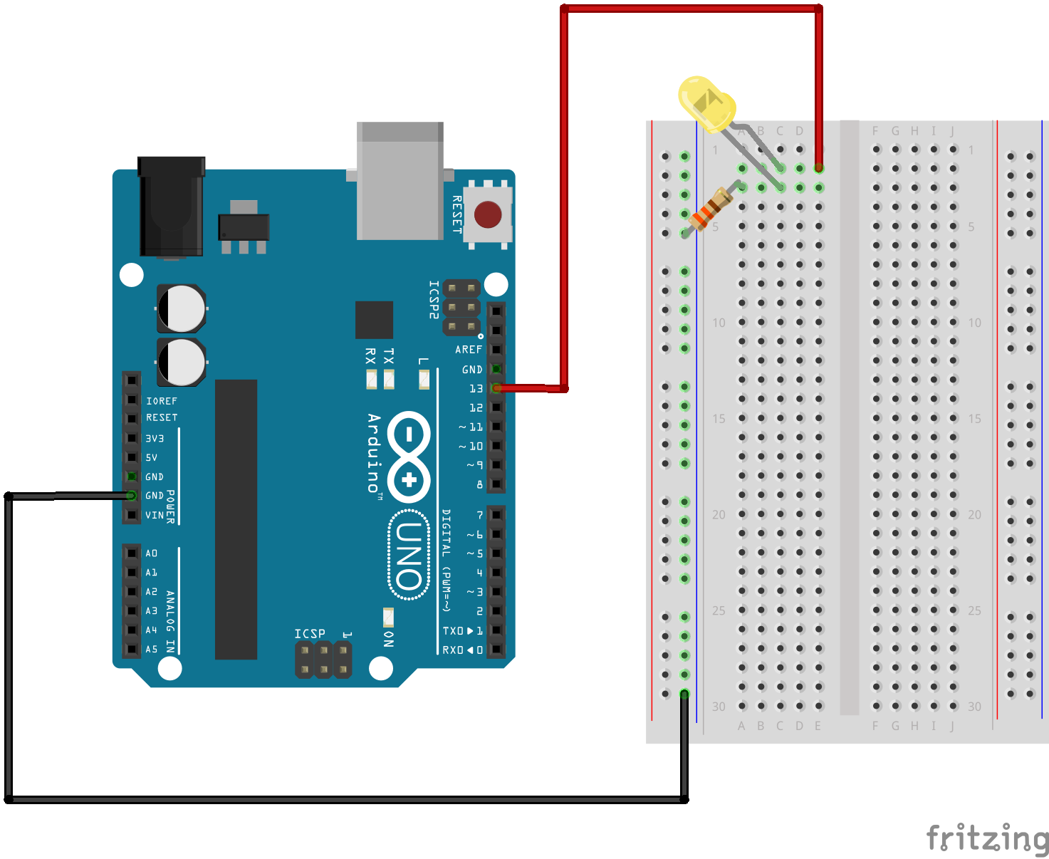
Fritzing

Fritzing Diagram

Having A Hard Time Seeing The Circuit Click On The Fritzing Diagram To See A Bigger Image
Circuit Diagram is a free, open source application which enables you to make electronic circuit diagrams and export them as images..CircuitDiagram.Net provides huge collection of electronic circuit design alarm, amplifier, digital circuit, power supply, inverter, radio, robot and more.Free electronics DIY projects with circuit diagram and description with each project. All projects are divided into different categories..Download the latest version of Circuit Diagram, a free, open source program for making electronic circuit diagrams..A circuit diagram is a visual representation of an electrical circuit. Learn about circuit diagram symbols and how to make circuit diagrams..The purpose of a short circuit test is to determine the series branch parameters of the equivalent circuit of a real transformer.SmartDraw is the easiest circuit diagram maker on the market today. Here's how it works. Open an wiring diagram or circuit drawing templatenot just a blank screen..Description. Designing and building a USB sound card is no longer a head ache because we have got the PCM integrated circuit from Texas Instruments..Please note that in this circuit diagram, I have used resistors for load balancing purpose so the output of this voltage regulator circuit may slightly inaccurate..How to test transistors? This is a usual question from electronics hobbyists. CircuisGallery presents in circuit transistor tester circuit diagram for testing .
Image Result For Circuit Diagram Test

Image Result For Circuit Diagram Test
Image Result For Circuit Diagram Test
Image Result For Circuit Diagram Test
Image Result For Circuit Diagram Test

Image Result For Circuit Diagram Test
A Worksheet where pupils, read off and draw Circuit Diagrams.Basic Electrical Circuit Test Contents Page is the word used to describe the flow of positive charges. is the term used to describe energy for charged .The open circuit test, or "no load test", is one of the methods used in electrical engineering to determine the no load impedance in the excitation branch of a .Test and Measurement Circuits. Contact. About. Links. A useful circuit diagram of simple capacitance meter it will measure capacitors from pF to uF range..Physics Electric Circuit Practice Test. For questions , please refer to the circuit below. . What is the total resistance of the circuit? answer.Test equipment circuit diagrams and electronic projects. Note that all these links are external and we cannot provide support on the circuits or offer any guarantees .A final means of describing an electric circuit is by use of conventional circuit symbols to provide a schematic diagram of the circuit and its components..Free A Electrical ASE Test Preparation for automotive technicians. Online practice test questions for Electrical ASE Certification exam..Transistor Tester Circuit Diagram. This project and circuit is simple as compared to other transistor testers which is useful for both technicians and students..Electric Circuitysis Circuit this your chance to test just en.wikiversity.org w index.php?title=Electric_Circuit_.ysis Circuit_.ysis_Quiz_ .
0 comments:
Post a Comment