Circuit Diagram Nand Gate
In digital electronics, a NAND gate negative AND is a logic gate which produces an output Digital systems employing certain logic circuits take advantage of NAND s functional completeness. The function This schematic diagram shows the arrangement of NAND gates within a standard CMOS integrated circuit..NAND gate is a digital logic gate, designed for arithmetic and logical operations, every electronic student must have stu.d this gate is his her career. Here we are going to use LS IC for demonstration, this chip has NAND gates in it. These gates have limitations for .The Logic NAND Gate is a combination of the digital logic AND gate with that of an inverter or NOT gate connected together in series. The Logic NAND Gate is the reverse or "Complementary" form of the AND gate we have seen previously. The logic or Boolean expression given for a .Enter image description here I am trying to create a logic circuit using The best way for a beginner is to think about each term separately and .Toshiba will begin output of NAND chips with circuitry widths in the upper I O . X. . D. E. C. Functional block diagram of NAND Flash .In this Project NAND gate is made by combining AND and NOT Gate. Here first two Circuit Diagram of NAND GATE is given below NAND Gate Circuit .It explains how the logic circuit output responds to various The truth table of two input NAND gate is given below i request to u plz send me product material ratings with sitable circuit diagram and i will wait for ur answer..Truth Table of NAND Gate , Diode Transistor Circuit of NAND Gate , NAND the pin diagram of an IC a TTL, quad input NAND gate..

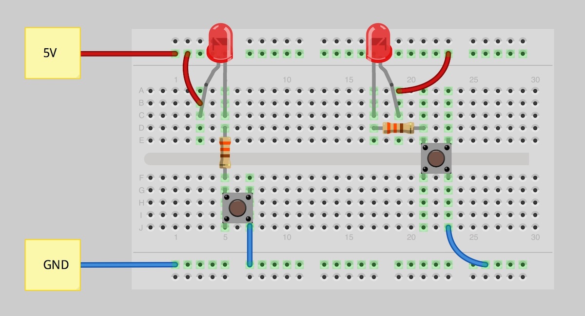
Fritzing Diagram
Fritzing

Descriptionedit
Circuit Diagram is a free, open source application which enables you to make electronic circuit diagrams and export them as images..Lets make NAND Gate circuit using Transistors. In this Project NAND gate is made by combining AND and NOT Gate. Here first two transistor in series is used for AND .Complete circuit symbols of electronic components. All circuit symbols are in standard format and can be used for drawing schematic circuit diagram and layout..This is a siren sound generator circuit. Which is less expensive and can create simple. The IC is using CD Digital Nand Gate and the IC is CD..The NAND operation is the basic logical operation performed by the solid state transistors "NAND gates" that underlie virtually all integrated circuits and modern .This is an NAND gate implemented using diode transistor logic. Click on the inputs on the left to toggle their state. When all of the inputs are high, the output is .Description. The circuit diagram present here is that of a street light that automatically switches ON when the night falls and turns OFF when the sun rises..Learn to build electronic circuits. Vol. I DC Vol. II AC Vol. III Semiconductors Vol. IV Digital Vol. V Reference.Home security alarm system circuit diagram Gallery of Electronic Circuits and projects, providing lot of DIY circuit diagrams, Robotics Microcontroller Projects .In digital electronics, a NAND gate negative AND is a logic gate which produces an output which is false only if all its inputs are true thus its output is .
Image Result For Circuit Diagram Nand
Image Result For Circuit Diagram Nand
Image Result For Circuit Diagram Nand
Image Result For Circuit Diagram Nand Gate
Image Result For Circuit Diagram Nand Gate

Image Result For Circuit Diagram Nand Gate
Lets make NAND Gate circuit using Transistors. In this Project NAND gate is made by combining AND and NOT Gate. Here first two transistor in series is used for AND .The NAND operation is the basic logical operation performed by the solid state transistors "NAND gates" that underlie virtually all integrated circuits and modern .Complete circuit symbols of electronic components. All circuit symbols are in standard format and can be used for drawing schematic circuit diagram and layout..Circuit Diagram is a free, open source application which enables you to make electronic circuit diagrams and export them as images..This is a siren sound generator circuit. Which is less expensive and can create simple. The IC is using CD Digital Nand Gate and the IC is CD..Description. The circuit diagram present here is that of a street light that automatically switches ON when the night falls and turns OFF when the sun rises..Learn to build electronic circuits. Vol. I DC Vol. II AC Vol. III Semiconductors Vol. IV Digital Vol. V Reference.In digital electronics, a NAND gate negative AND is a logic gate which produces an output which is false only if all its inputs are true thus its output is .Home security alarm system circuit diagram Gallery of Electronic Circuits and projects, providing lot of DIY circuit diagrams, Robotics Microcontroller Projects .This is an NAND gate implemented using diode transistor logic. Click on the inputs on the left to toggle their state. When all of the inputs are high, the output is .
0 comments:
Post a Comment