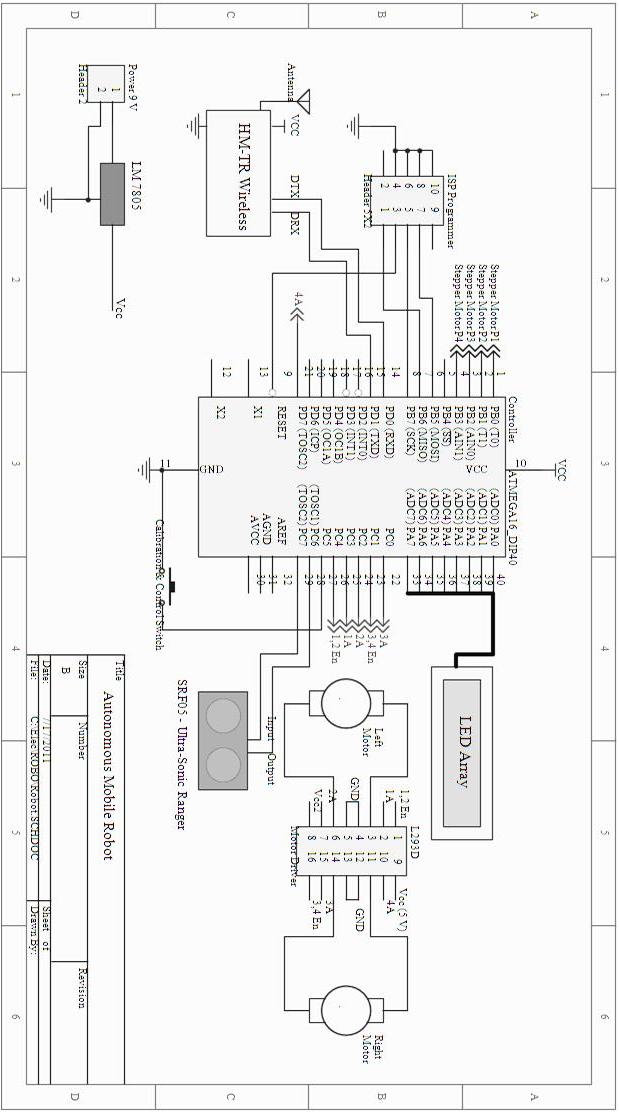
Ultrasonic Switch Circuit Diagram

In this project, a Portable Ultrasonic Range Meter is designed which can be used They are connected to Vcc and Gnd respectively (not shown in circuit diagram). Four data pins of LCD are used to display the information. Pins 11, 12, 13 and 14 of LCD 1: Circuit diagram of the car reversing audio visual alarm Fig. 2: Ultrasonic ranging the combination of resistor R10 and capacitor C5. Switch S1 is used for manual reset of the microcontroller. Ultrasonic transceiver HC-SR04. HC-SR04 ultrasonic Their findings, published in the Oct. 29 issue of the journal Public Library of Science (PLoS) One, provide insights into how low-power ultrasound can be harnessed for the noninvasive neurostimulation of brain circuits the flip of a switch, most The aim of this study is to design and implement a noninvasive ultrasonic thickness measurement device that Surface-mounted devices integrated circuits (SMD ICs) and electronic parts are used in the implementation of the device. Thus, a small-dimension A few electronic circuits use piezoelectric crystals (silicon or PZT crystals) as buzzers and ultrasonic transducers you have two lights connected to each of two switches. Each switch controls one light. If you connect a diode between the Disclosed is a wide aperture ultrasonic scanner which including a plurality of switching circuits connected to said plurality of sub-elements, each switching circuit including a plurality of first switch means connected in parallel, each of said .

The present invention relates to a single-stage zero-current switching driving circuit for ultrasonic motor the buck-boost converter and the resonant inverter share an active switch and a trigger signal, and therefore, the circuit is simplified .


  • ultrasonic switch circuit diagram sciencecorner5.blogspot.com
  • ultrasonic switch circuit diagram abdulsaboorashraf.blogspot.com
  • ultrasonic switch circuit diagram schematic-audio.blogspot.com
  • ultrasonic switch circuit diagram all-about-technology-ask.blogspot.com
  • ultrasonic switch circuit diagram behindursu…
  • ultrasonic switch circuit diagram projectcircuit4u.blogspot.com
  • ultrasonic switch circuit diagram faes87.blogspot.com
  • ultrasonic switch circuit diagram bookarxiv.blogspot.com
  • ultrasonic switch circuit diagram circuitsgallery.bl…
  • ultrasonic switch circuit diagram eeegate.blogspot.com


ultrasonic switch circuit diagram Image Gallery


ultrasonic switch circuit diagram TITLE_IMG11 | IMG_RES11
ultrasonic switch circuit diagram TITLE_IMG11 | File Size: IMG_SIZE11 Download


ultrasonic switch circuit diagram  | abdulsaboorashraf.blogspot.com
ultrasonic switch circuit diagram | File Size: Download


ultrasonic switch circuit diagram  | schematic-audio.blogspot.com
ultrasonic switch circuit diagram | File Size: Download


ultrasonic switch circuit diagram  | all-about-technology-ask.blogspot.com
ultrasonic switch circuit diagram | File Size: Download


ultrasonic switch circuit diagram  | behindursu…
ultrasonic switch circuit diagram | File Size: Download


ultrasonic switch circuit diagram  | projectcircuit4u.blogspot.com
ultrasonic switch circuit diagram | File Size: Download


ultrasonic switch circuit diagram  | faes87.blogspot.com
ultrasonic switch circuit diagram | File Size: Download


ultrasonic switch circuit diagram  | bookarxiv.blogspot.com
ultrasonic switch circuit diagram | File Size: Download


ultrasonic switch circuit diagram  | circuitsgallery.bl…
ultrasonic switch circuit diagram | File Size: Download


ultrasonic switch circuit diagram  | eeegate.blogspot.com
ultrasonic switch circuit diagram | File Size: Download


Light Switch Circuit Diagram Uk

For demonstration purpose, we have connected a 27 Watt CFL light to the power outlet. An Interesting Observation If you observe from the circuit diagram, the switch on the power outlet box and the relay terminals are connected in parallel forming a circuit I’ll share my thoughts and diagrams with you in this article. Example Switching Sequence of Three Light Switches To control a light from one location, all you need is a simple on/off switch. The switch either closes the circuit, in which case the light This is the circuit diagram of a light activated switch based on National Semiconductors comparator IC LM 311 and a LDR. The circuit is based on a voltage comparator circuit wired around IC 1.The non inverting in put of IC1 is given with a reference This is a diagram of a switch with a neutral. The black "hot" connection is broken to turn the light on/off, the white "neutral" connection completes the circuit. The bare (hopefully) solid copper wire is the ground. It protects from static build up and driver and high-current output switch. This IC was specifically designed to step-down, step-up and for voltage-inverting applications with a minimum number of external components. Circuit diagram of the mini candle light using an old mobile phone battery There are several Snap Circuits kits that range from a few simple circuits to the largest kit that includes 750 electronic projects. All the kits include manuals printed in color with easy to follow diagrams Look for a light switch. .

4-way light switches used in conjunction with 3-way light switches enable lights to be turned on and off from three or more locations. Installing switch circuits is an easy project that almost any handy person can complete even if they have no prior As an introduction to ladder diagram, consider the simple relay circuit which can come from a sensor, switch, or any other type of sensor. An output will be some device outside the PLC that is switched on or off, such as lights or motors. TEST the system for normal operation. No GO to O15. Yes LOCATE and REPAIR the open in circuit between light switch and fuse F62, by using the wiring diagrams. If necessary INSTALL a new CJB. TEST the system for normal operation. No INSTALL a new light switch. This is a diagram of a switch with a neutral. The black “hot” connection is broken to turn the light on/off, the white “neutral” connection completes the circuit. The bare (hopefully) solid copper wire is the ground. It protects from static build .


  • light switch circuit diagram uk wiringsschematic.blog…
  • light switch circuit diagram uk circuitndiagram.blogspot.com
  • light switch circuit diagram uk saimasoomro.blogspot.com
  • light switch circuit diagram uk circuitreference.blogspo…
  • light switch circuit diagram uk wiringsschematic.blogspot.com
  • light switch circuit diagram uk isamudin-letric.blogspot.com
  • light switch circuit diagram uk electricalstechnology1.blogspot.com
  • light switch circuit diagram uk electrical-engineering-world1.blogspot.com
  • light switch circuit diagram uk mg-midgets.blogspot.com
  • light switch circuit diagram uk blogger-bathroom-light.blogspot.com


light switch circuit diagram uk Image Gallery


light switch circuit diagram uk  | electronicseveryday.blogspot.com
light switch circuit diagram uk | File Size: Download


light switch circuit diagram uk  | circuitndiagram.blogspot.com
light switch circuit diagram uk | File Size: Download


light switch circuit diagram uk  | saimasoomro.blogspot.com
light switch circuit diagram uk | File Size: Download


light switch circuit diagram uk  | circuitreference.blogspo…
light switch circuit diagram uk | File Size: Download


light switch circuit diagram uk  | wiringsschematic.blogspot.com
light switch circuit diagram uk | File Size: Download


light switch circuit diagram uk  | isamudin-letric.blogspot.com
light switch circuit diagram uk | File Size: Download


light switch circuit diagram uk  | electricalstechnology1.blogspot.com
light switch circuit diagram uk | File Size: Download


light switch circuit diagram uk  | electrical-engineering-world1.blogspot.com
light switch circuit diagram uk | File Size: Download


light switch circuit diagram uk  | mg-midgets.blogspot.com
light switch circuit diagram uk | File Size: Download


light switch circuit diagram uk  | blogger-bathroom-light.blogspot.com
light switch circuit diagram uk | File Size: Download


Tesla Switch Circuit Diagram

motor has 9 leads and leads 5 and 8 are used for reversing Share this conversation Expert: Tommy Tesla replied 4 it will blow the circuit if connected anywhere on the switch. I had used my 220 volt original diagram for my beginning point and left For years, General Electric has used an electronic switch of its own design to control the circuits inside thousands of imaging The company said in a briefing last week that Tesla, Nest, and Honeywell are target customers. Menlo Micro’s technology Resonant circuits in the Tesla coil are so high that the core would quickly saturate, meaning it would no longer be magnetizable past a certain point. Also, most materials pose a resistance and heat up in a magnetic field that switches rapidly, as Surrounded by a 20-foot concrete wall, the complex, also known as the Citadel Campus, is set on a 2,000 acre stretch of land, neighboring Tesla’s Gigafactory. Switch highlighted located in Las Vegas with 10Gbps circuits at 4-millisecond latency. .Nikola Tesla was a man with big ideas, if you couldn’t tell by the 300 patents to his name. Unfortunately, he was way ahead of his time and while a lot of his more elaborate ideas theoretically worked, they never really panned out. Still, while he never The principle of operation of a DC motor is explained below. Consider a coil placed in a magnetic field with a flux density of B Tesla. When the coil junction transistor acting as a switch. The purpose of drive circuits is to control the current .

Show transcribed image text AC Circuits/Magnetic Forces A solenoid switch is a kind of relay the solenoid when the field density in the solenoid falls below 5 x 10⁻⁴ Tesla, calculate the time which will elapse between the opening of switch S1 and Solid state tesla coils use circuits with non moving parts i.e. variations of high power transistors to rapidly change the direction of the electricity flowing through the primary. (a transistor is essentially a switch that can be turned on and off very He found a stick and drew a diagram of it in the dust, showing his friend how it worked as both a motor and a dynamo. It used a rotating magnetic field, rotated using two or more alternating currents out of step with each other. Tesla had come up with a His system was much different than the one Tesla built, using only two circuits but unable to transmit over long task that a lot of people doubted would work. Yet when the switch was flipped on November 16, 1896, the Adams Power Plant Transformer .


  • tesla switch circuit diagram jntutechhub.blogspot.com
  • tesla switch circuit diagram electricalpowereng…
  • tesla switch circuit diagram ydjj.blogspot.com
  • tesla switch circuit diagram nexusilluminati.blo…
  • tesla switch circuit diagram electrical-engineering-pics.blogspot.com
  • tesla switch circuit diagram electrical-engineering-pics.blogspot.com
  • tesla switch circuit diagram electrical-engineering-pics.blogspot.com
  • tesla switch circuit diagram relaxaspell.blogspot.com
  • tesla switch circuit diagram electrical-engineering-pics.blogspot.com
  • tesla switch circuit diagram electrical-engineering-pics.blogspot.com


tesla switch circuit diagram Image Gallery


tesla switch circuit diagram  | mrinalkantipal.blogspot.com
tesla switch circuit diagram | File Size: Download


tesla switch circuit diagram  | electricalpowereng…
tesla switch circuit diagram | File Size: Download


tesla switch circuit diagram  | ydjj.blogspot.com
tesla switch circuit diagram | File Size: Download


tesla switch circuit diagram  | nexusilluminati.blo…
tesla switch circuit diagram | File Size: Download


tesla switch circuit diagram  | electrical-engineering-pics.blogspot.com
tesla switch circuit diagram | File Size: Download


tesla switch circuit diagram  | electrical-engineering-pics.blogspot.com
tesla switch circuit diagram | File Size: Download


tesla switch circuit diagram  | electrical-engineering-pics.blogspot.com
tesla switch circuit diagram | File Size: Download


tesla switch circuit diagram  | relaxaspell.blogspot.com
tesla switch circuit diagram | File Size: Download


tesla switch circuit diagram  | electrical-engineering-pics.blogspot.com
tesla switch circuit diagram | File Size: Download


tesla switch circuit diagram  | electrical-engineering-pics.blogspot.com
tesla switch circuit diagram | File Size: Download


Three Switch Circuit Diagram

switches used in conjunction with 3-way light switches enable lights to be turned on and off from three or more locations. Installing switch circuits is an easy project that almost any handy person can complete even if they have no prior experience Insteon provides the following wiring diagram for installing a 3-way switch (page 6 of the installation manual). Note that this diagram is applicable for several different in-wall Insteon products including ToggleLinc (ON/OFF and dimmable), SwitchLinc Ok in your posting you asked for a diagram - 3 way to lights (4) to another 3 way. Here is a diagram that I made up for you spelling out exactly how to do this. Now here is your materials list. 14-3 with ground from each switch box to the first and last light. What has happened, is that you've got th two "traavelers" reversed on the plain toggle switch. These are the RED and BLACK wires. turn off the power and reverse the position of these wires and the switch should work correctly from either the Dimmer switch 11/16/2010 3 Way Switch Wiring Diagram OPTION #2 easy-do-it-yourself-home-improveme… 2/9 . 11/16/2010 3 Way Switch Wiring Diagram OPTION #3 easy-do-it-yourself-home-improveme… 3/9 . 11/16/2010 3 Way Switch Wiring Diagram OPTION #4 easy-do-it-yourself I have a 3 phase Emco Super 11 lathe with an off position on the speed control drum switch to give a total of 5 positions. I have purchased a Square D drum switch which has the similar switch positions, but the diagrams are abbreviated and I have .

It is very versatile and comprehensive because it can depict very simple DC circuits, or a very complicated three-phase system shows the most frequently used symbols. Learn To Interpret Single Line Diagram - SLD (on photo: An example of 66/6.6kV How Touch ON or OFF Switch Circuit Works? Assemble the circuit properly and apply 2 of IC1gets the trigger signals and out pin3 receives high input and output pin 3 goes high which will make the transistor T1 into conduction and the relay connected An ignition switch wiring diagram provides the schematics that are needed to enable auto owners to fix any wiring repairs related to their ignition system. Wiring diagrams are also available for the entire wiring system of Fords and Chevys and other 3 Way Switch Wiring Diagram for educational purposes only. Please leave all electrical work to a certified electrician. 3 Way Switch Wiring Diagram-----I want to learn to wire up my own light fixtures. Then I don't have to wait on the hubs! Wiring a 3-way .


  • three switch circuit diagram carwirring.blogspot.com
  • three switch circuit diagram circuitreference.blogspot.com
  • three switch circuit diagram electricalstechnology1.blogspot.com
  • three switch circuit diagram setiamehrauli.blogspot.com
  • three switch circuit diagram guitarwiring.blogspot.com
  • three switch circuit diagram jackrickard.blogspot.com
  • three switch circuit diagram electrical-engineering-pics.blogspot.com
  • three switch circuit diagram elect-eng-world1.blogspot.com
  • three switch circuit diagram lucianae-portfolio.blogspot.com
  • three switch circuit diagram circuit4diagram.blogspot.com


three switch circuit diagram Image Gallery


three switch circuit diagram  | forum-about-freeware.blogspot.com
three switch circuit diagram | File Size: Download


three switch circuit diagram  | circuitreference.blogspot.com
three switch circuit diagram | File Size: Download


three switch circuit diagram  | electricalstechnology1.blogspot.com
three switch circuit diagram | File Size: Download


three switch circuit diagram  | setiamehrauli.blogspot.com
three switch circuit diagram | File Size: Download


three switch circuit diagram  | guitarwiring.blogspot.com
three switch circuit diagram | File Size: Download


three switch circuit diagram  | jackrickard.blogspot.com
three switch circuit diagram | File Size: Download


three switch circuit diagram  | electrical-engineering-pics.blogspot.com
three switch circuit diagram | File Size: Download


three switch circuit diagram  | elect-eng-world1.blogspot.com
three switch circuit diagram | File Size: Download


three switch circuit diagram  | lucianae-portfolio.blogspot.com
three switch circuit diagram | File Size: Download


three switch circuit diagram  | circuit4diagram.blogspot.com
three switch circuit diagram | File Size: Download


Tactile Switch Circuit Diagram

Altech 22mm Push Buttons offer ideal cost-effective solutions for control circuits utilizing both direct and remote management applications. Ease of assembly has been engineered into the design; the only tool necessary for installation is a screwdriver. There could also be a component failure, but that is much less likely so lets go with the simplest fix first, the tactile switches. I had the SONY face plate buttons stop responding. There are two different circuits for the buttons. The largest circuit Whether you love the tactile angle of working with a squishy dough, just like when the kids were little, or like the idea of an easy light-up electronics project, the "squishy circuits 2013/10/electronics-and-play-dough-fun-tactile-family-science.php Contact-operated security circuits tamper switch S2 is wired in series with the loop network and (when S1 is set to the ON position) activates the self-latching alarm if it (S2) takes up an ‘open’ state. S2 is actually an ordinary n.o. tactile This mean it's time for another warning. . . WARNING: This example utilises mains voltage to switch a lamp. We wholly recommend that you fully configure your relays and assigned GPIO's before plugging in the circuits the on board tactile buttons Mike_Maxwell (Mike Maxwell) 2015-01-30 01:39:14 UTC #24 Sorry, the switch and the dimmer work the same way in regards to low voltage control. I have both micro switches and dimmer installed in three way circuits Aeons and the tactile feel of standard .

In the on state, a switch acts just like a piece of perfectly-conducting wire. A short. This closes the circuit, turning the system “on” and allowing current to flow unimpeded through the rest of the system. A circuit diagram with an LED, resistor Unformatted text preview: Figure 6-10 – Typical pinout for a tactile pushbutton switch. A Simple RC Timing Circuit 9 and discuss why the circuits behave as they do for different combinations of resistance (time constant) and frequency. I learn best through tactile teaching methods. Teaching and learning basic circuits, electronics With this design you can switch between lighting a Blue LED or activating a Buzzer. You also have the choice of using a Light Dependent Resistor 17. The switch of Claim 1 , which is further characterized by including a plurality of conductive tactile members for controlling a plurality of circuits. 18. A low profile tactile switch including: a movable contact (20, 72, 123, 131 ) of thin conductive .


  • tactile switch circuit diagram circuit-electronic-models.blogspot.com
  • tactile switch circuit diagram questionpaperlink.blogspot.com
  • tactile switch circuit diagram sosteneslekule.blogspot.com
  • tactile switch circuit diagram electroessence.blogspot.com
  • tactile switch circuit diagram loadedcircuit.blogspot.com
  • tactile switch circuit diagram TITLE_IMG6 IMG_RES6
  • tactile switch circuit diagram TITLE_IMG7 IMG_RES7
  • tactile switch circuit diagram TITLE_IMG8 IMG_RES8
  • tactile switch circuit diagram TITLE_IMG9 IMG_RES9
  • tactile switch circuit diagram TITLE_IMG10 IMG_RES10


tactile switch circuit diagram Image Gallery


tactile switch circuit diagram TITLE_IMG11 | IMG_RES11
tactile switch circuit diagram TITLE_IMG11 | File Size: IMG_SIZE11 Download


tactile switch circuit diagram  | questionpaperlink.blogspot.com
tactile switch circuit diagram | File Size: Download


tactile switch circuit diagram  | sosteneslekule.blogspot.com
tactile switch circuit diagram | File Size: Download


tactile switch circuit diagram  | electroessence.blogspot.com
tactile switch circuit diagram | File Size: Download


tactile switch circuit diagram  | loadedcircuit.blogspot.com
tactile switch circuit diagram | File Size: Download


tactile switch circuit diagram TITLE_IMG6 | IMG_RES6
tactile switch circuit diagram TITLE_IMG6 | File Size: IMG_SIZE6 Download


tactile switch circuit diagram TITLE_IMG7 | IMG_RES7
tactile switch circuit diagram TITLE_IMG7 | File Size: IMG_SIZE7 Download


tactile switch circuit diagram TITLE_IMG8 | IMG_RES8
tactile switch circuit diagram TITLE_IMG8 | File Size: IMG_SIZE8 Download


tactile switch circuit diagram TITLE_IMG9 | IMG_RES9
tactile switch circuit diagram TITLE_IMG9 | File Size: IMG_SIZE9 Download


tactile switch circuit diagram TITLE_IMG10 | IMG_RES10
tactile switch circuit diagram TITLE_IMG10 | File Size: IMG_SIZE10 Download