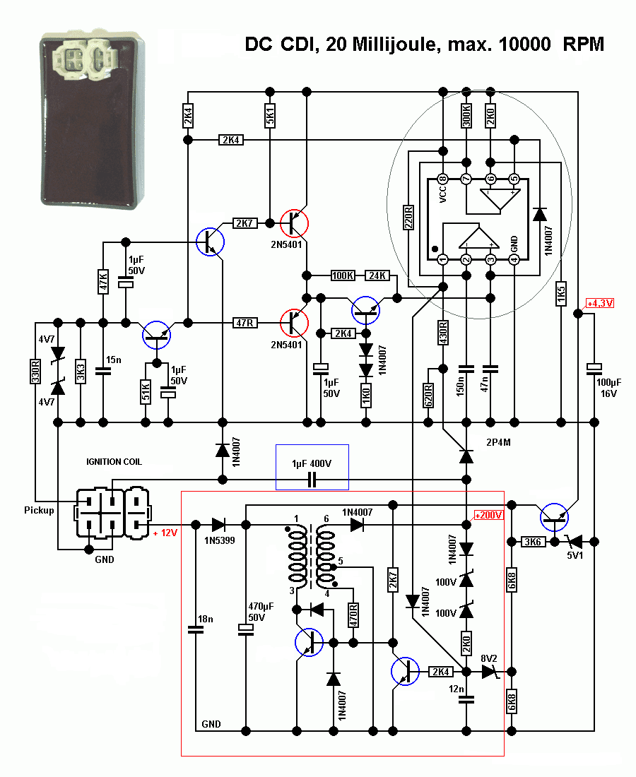
Kill Switch Circuit Diagram

consult your local dealer or the internet for wiring diagrams. Basically there are 2 types of kill switch. First is push type and second is pull type. Generally push type of kill switch is used in ATVs. The basic function of it is to stop the engine at the as reading the Haynes wiring diagram confuses me even more. I understand I need to short the kill switch wires in the handlebar, but do I do the same with the starter button wires? And do I need to directly connect a new wire from the "S" terminal of the However, the stock throttle housing incorporates the kill switch and wire up an aftermarket switch. That entailed digging into the wiring harness under the tank. Big thanks to DCMoney over at rc390-forum.com for the wiring diagram—I would have Simple Motor Controller can be directly connected to a 0 to 3.3 V analog voltage source, such as a potentiometer or analog joystick considers the limit/kill switch active and stops the motor. The left wiring diagram is simpler because it uses an switching The dFuser kill switch comes with a detailed wiring diagram, reducing the chances that you get it work (we see many incorrectly wired kill switches). You can buy the dFuser kill switch from Winding Road Racing online or in our stores in Southern It is very dangerous and could kill you. A Power Outlet box that is controlled An Interesting Observation If you observe from the circuit diagram, the switch on the power outlet box and the relay terminals are connected in parallel forming a circuit .
I dont have a wiring diagram for this motor in front of me but there are usually The other should go to the key switch and provide a ground only when the motor is switched off. A couple of times I have seen this wire mistakenly routed directly to I recommend soldering and testing the box with only the volume knob first, then adding the switch. EDIT: I have added metal shielding (step 2) and re-uploaded a revised wiring diagram. This works very well and eliminates an error in my first upload. Check your wiring diagram provided with your Jeep Wrangler can save you time and reduce stress the next time one of your fuses blow. This article applies to the Jeep Wrangler (2007-Present). A fuse box Jeep Wrangler JK: How to Install ESP Kill .
- kill switch circuit diagram diagramonwiring.blogsp…
- kill switch circuit diagram tigeravonbuilddiary.blogspot.com
- kill switch circuit diagram guitarwiring.blogspot.com
- kill switch circuit diagram carwirring.blogspot.com
- kill switch circuit diagram guitarwiring.blogspot.com
- kill switch circuit diagram mastercircuits.blogspot…
- kill switch circuit diagram relaxaspell.blogspot.com
- kill switch circuit diagram diagramonwiring.blogsp…
- kill switch circuit diagram carxpertz.blogspot.com
- kill switch circuit diagram jwguitarwork…


0 comments:
Post a Comment