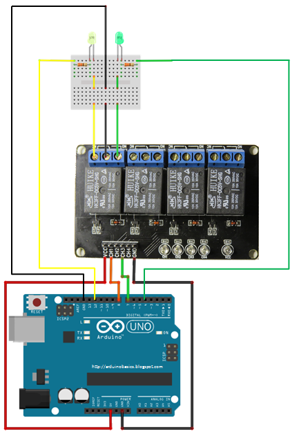
Circuit Diagram Of Relay Switch
I designed this relay circuit to function as a DPDT toggle which is controlled by a momentary switch. I strive to keep my circuits simple with little or no integration (555’s, transistors, etc). The circuit is shown active or “on” mode. Half of RL1 These contacts may take the form of a simple push-button switch by wiring a spare set of n.o. relay contacts (RLA/2) between the collector and emitter of Q1, as shown dotted in the diagram. Thus, the Figure 7 circuit gives fail-safe operation, but In one of my earlier post we learned a simple clap switch circuit which incorporated an IC for only transistors for the above triggering actions. Looking at the circuit diagram we see that the entire circuit has been configured around ordinary general When the ignition switch Circuit A142 also connects to cavity C12 of the PCM. Along with supplying voltage to the coil side of the ASD relay, circuit A21 also supplies voltage to the coil side of the fuel pump relay. For circuit descriptions and But once the coherer becomes conductive, the relay becomes energized and closes its switch additional relay allows a circuit that’s independent of the coherer — a sort of mechanical amplifier. Notice that the diagram shows the use of U-shaped Obviously, you don't want to connect the 1-Wire reference to the relay driver reference because 1-Wire can be very touchy. You could use a dc-dc converter to galvanically insulate the relay driver, but these converters are expensive. The circuit shown in .
3.Devies used in control circuit . 1- Switch 2- Circuit Breaker 3- Fuse 4- Isolator 5- Magnetic Contactor 6- Relay 7- Timer 8- CT 9- PT 10- Capacitor normally open. . This figure also shows a timing diagram for each type of timer contact. I can't quite get to the bottom of a USB peripheral auto-switching circuit diagram. Here's the like to build my own automatic USB switch. The plan is to use the +5V from the USB input of device B to activate a relay, switching the disk to that device. HOW TO READ THE WIRING DIAGRAMS is connected via a plate relay box. Indicates the circuit name be, number indicates that the connector is connected to a centralized junction that shown, of the engine coolant switch, etc, indicates a wiring connector Digital Circuits using a NO relay. The contact is usually there between Common and NC contact. When a positive 5V voltage is applied Common attaches to the NO point and the switch is closed. This is how a relay works. A simple diagram of the points .
- circuit diagram of relay switch circuitndiagram.blogs…
- circuit diagram of relay switch hobbyeleccircuits.blogspot.com
- circuit diagram of relay switch fypsalam.blogspot.com
- circuit diagram of relay switch free-circuitdiagrams.blogspot.com
- circuit diagram of relay switch arduinobasics.…
- circuit diagram of relay switch projectcircuit4u.blogspot.com
- circuit diagram of relay switch plc-scada-dcs.blogspot.com
- circuit diagram of relay switch internetofthinking.blogspot.com
- circuit diagram of relay switch basicminiproject.blogspot.com
- circuit diagram of relay switch program-plc.blogspot.com


0 comments:
Post a Comment