Switch Circuit Diagram Logic

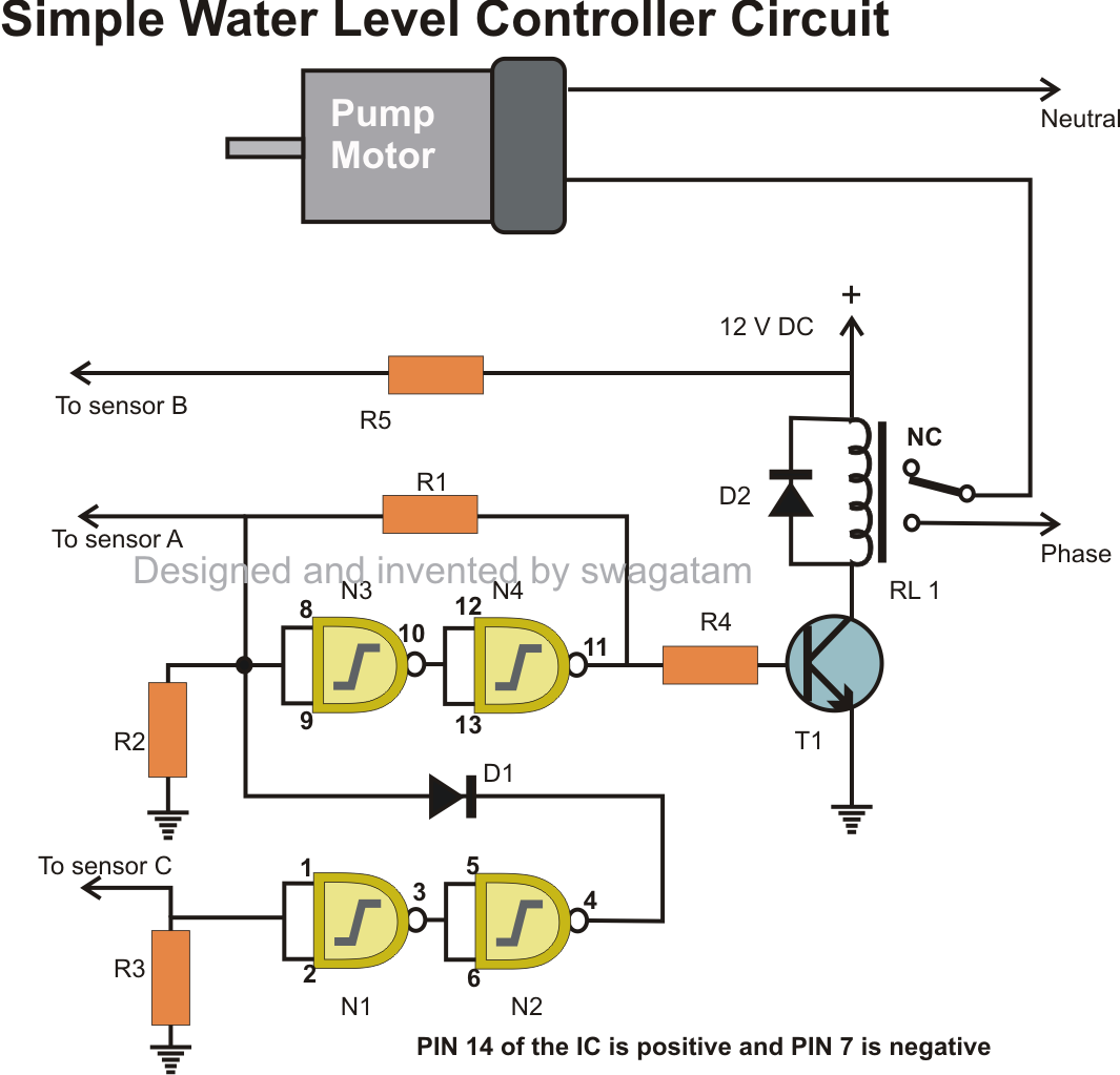
A simple touch switch circuit using CD4011 is given here Since the pins 9 and 13 are connected to the positive via resistors R1 and R2, the logic gates of the ICs will be in high state. When we touch through the points A, B the gates of the IC will The NEM switch can be used to form digital logic circuits including NAND gates, NOR gates, programmable logic gates, and SRAM and DRAM memory cells which can be used in place of conventional CMOS circuits, or in combination therewith. a source electrode Get up to speed with the future of logic switch design with this indispensable overview of the most promising successors to modern CMOS transistors. Learn how to overcome existing design challenges using novel device concepts, presented using an in-depth Functional diagram and truth table of the 4502B Hex three-state inverter with INHIBIT control. Alternatively, either CMOS Schmitt inverter can be used as a switch-on pulse generator (which generates a brief logic 1 switch-on output pulse when the circuit This paper qualitatively explores the performance limits, i.e., energy vs. frequency, of adiabatic logic circuits based on nanoelectromechanical (NEM) switches. It is shown that the contact resistance and the electro-mechanical switching behavior of the Electrical engineers at the Technische Universität München (TUM) and the University of Notre Dame have devised a new type of building block for digital integrated circuits as a programmable switch in a digital circuit. Magnetic circuits offer several .
all of these sensors can be simulated with switches for input and LEDs for output. The Logic Interface board besides operating in a static mode also has a clock circuit to simulate dynamic operation of logic circuits which is closer actual circuit To use the simulator one can click and drag logic gates and other elements onto the page and connect them to form circuits. Notice that the cicuit loaded initially involves a single AND gate. Click the upper toggle switch. The top-most LED (the A LED This paper describes a new approach for logic simulation of bipolar digital circuits. The approach is based on the development of a switch-level model of the transistor and on representing the circuit by a switch-graph. The method automatically partitions The various pinout functions of the IC can be learned from the following points: The supply positive is applied to pin#8 and ground to pin#1 (negative) The touch signal on the touch pad is sent to pin#2, and the logic is transformed into an ON or OFF at .
- switch circuit diagram logic circuitdiagramsof.blogspot.com
- switch circuit diagram logic easycircuit012.blogspot.com
- switch circuit diagram logic homemadecircuitsand…
- switch circuit diagram logic plcmaster8285.blogspot.com
- switch circuit diagram logic plc-scada-dcs.blogspot.com
- switch circuit diagram logic cidigg.blogspot.com
- switch circuit diagram logic electronicsirfan.blogspot.com
- switch circuit diagram logic simulationofinverters.blogs…
- switch circuit diagram logic burglaralarmves.blogspot.com
- switch circuit diagram logic articlesece.blogspot.com


0 comments:
Post a Comment