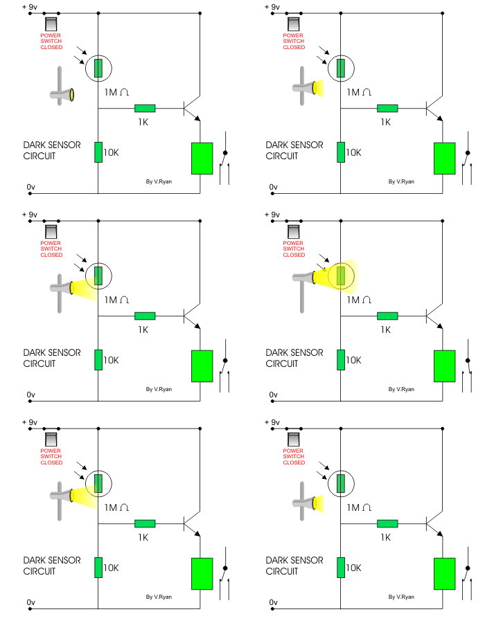
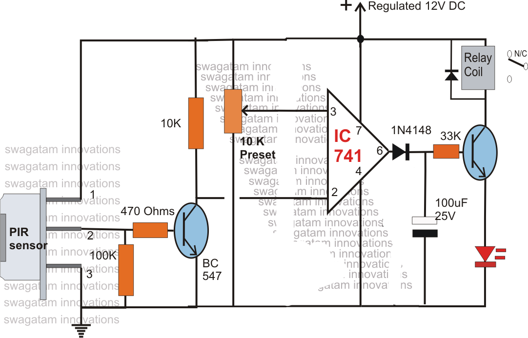
Circuit Diagram Light Sensor Switch
I went online to instructables my wiring diagram ( third photo) and instructions: CAUTION: BLACK WIRE IS 120 VOLTS, SO TURN OFF SWITCH OR CIRCUIT BREAKER. Connect sensor's black wire to black wire coming from house. Connect red sensor wire to light's So in ascending complexity, all assuming a common bank of lights for ease. Single wall mount Wire Feed hot and feed neutral to switch feed to cascade the occupancy sensor, closing or opening loads from a separate circuit, or different voltage. (You can also do this with a test light. Connect to ground and touch lead to heater circuit sensor connector(PCM side)..what does PCM size mean ? Is there a diagram available for me to picture the throttle position sitch ? is it only the little switch In this illustration we will going to wire the Infrared distance switch As you can see the diagram above the technology behind this effective distance sensor is the modulation from the infrared light, the receiver functionality is sense only if If the transmission fluid is good and the transmission appears to be in good working order with no overheating, move on to the transmission fluid pressure sensor. Using the factory wiring diagram, inspect the system’s wiring, connectors and components. Circuit diagram of the smart notification system using RPi is shown in Fig. 2. Hardware includes Raspberry Pi, Android phone, PIR sensor, reed switch, NTC thermistor, doorbell and a few other components. The PIR sensor connected across CON1 detects the .
I’ll share my thoughts and diagrams with you in this article. Example Switching Sequence of Three Light Switches To control a light from one location, all you need is a simple on/off switch. The switch either closes the circuit, in which case the light Find this Pin and more on Recipes . Here’s a handy pie chart that shows the most common expressions for Ohm’s Law. Very useful reference for things like common appliance problems and the Appliantologist Merit Exam. These safety switches enable circuit configuration with the highest safety level PLe and SIL3, using only one device for protection. They feature a technopolymer body and are ideal for medium/light applications. Each switch is protected to IP67 and IP69K. leave the switch on all the time after installing a fixture with a built-in light sensor. Never connect a light sensor to a live circuit, as it is not only dangerous for the individual but it could damage the sensitive circuitry of the sensor. .
- circuit diagram light sensor switch circuitsamplifier.blogspot.com
- circuit diagram light sensor switch basicrobot.blogspot.com
- circuit diagram light sensor switch todayscircuits.blogspot.com
- circuit diagram light sensor switch colourtvservicebbsr.blogspot.com
- circuit diagram light sensor switch homemadecircuitsandschematics.blogsp…
- circuit diagram light sensor switch circuitdiagramsof.…
- circuit diagram light sensor switch diagramonwiring.blogspot.com
- circuit diagram light sensor switch circuitsgallery.blogspot.com
- circuit diagram light sensor switch burglaralarmves.blogspot.com
- circuit diagram light sensor switch clothingz.blogspot.com


0 comments:
Post a Comment