Circuit Diagram Multimeter
SCHEMATIC DIAGRAM. ILLUSTRATION. INSTRUCTIONS. First, you need to determine the characteristics of your meter movement. Most important is to know .The solid state electronic multimeter or VOM generally consists of the The schematic diagram of a balanced bridge dc amplifier using two .This is Digital multimeter circuit using ICL. dc digital meter circuit to smart full function, measure DCV, In Figure the schematic diagram of this project..Page . . CIRCUIT DIAGRAMS AND COMPONENT DRAWINGS Similar toog ones, digital multimeter Figure b has a dial to select its function..A typical multimeter may include features such as the ability to measure voltage, current and resistance. Multimeters may useog or digital circuits.og .Digital multimeters block diagram Electronic Products. Keithley DMM blk diagram. Digital multimeters convert CircuitBlockDiagrams..Use is the inexpensive, accurate, digital multimeter DMM presented here an Figure shows the circuit diagram of the ADD based DMM, and Table .Do you have any idea about digital multimeter working principle? If not then you are at right place here we explain you its principle, symbols, block diagram most advanced instruments that make use of modern Integrated circuits for making .When you take measurements with a multimeter, you will need to decide whether to attach it to your circuit .
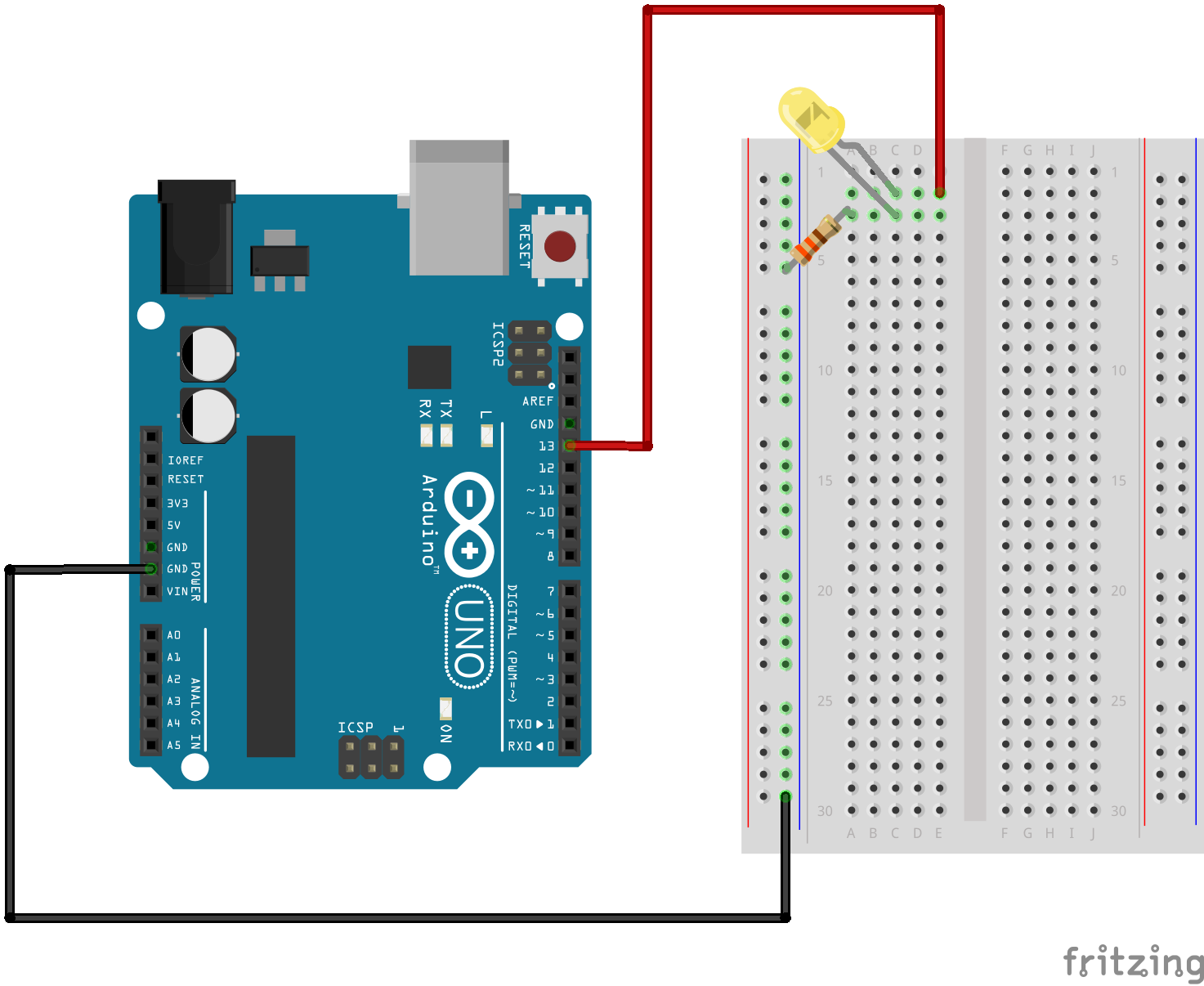
Fritzing

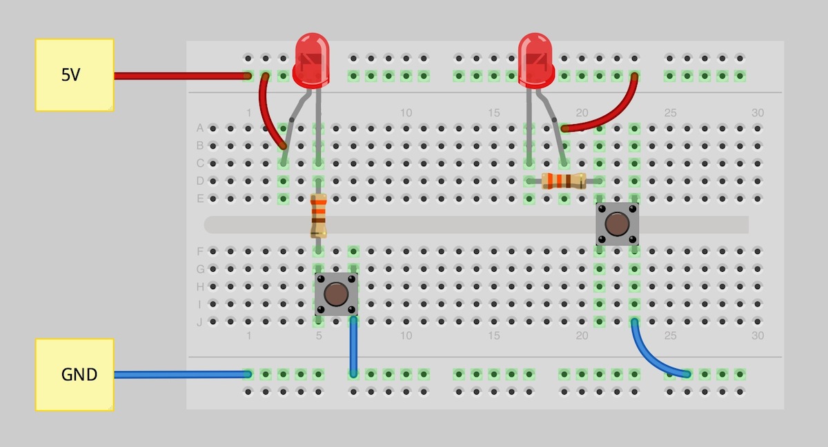
Fritzing Diagram

Having A Hard Time Seeing The Circuit Click On The Fritzing Diagram To See A Bigger Image
MEASURING VOLTAGE Most of the readings you will take with a multimeter will be VOLTAGE readings. Before taking a reading, you should select the highest range and .How to test transistors? This is a usual question from electronics hobbyists. CircuisGallery presents in circuit transistor tester circuit diagram for testing .This simple digital voltmeter circuit diagram is a saving, easy to use by CA CAas main, digit numeric display LED segment, V power supply.Most simple FM transmitter circuit diagram Gallery of Electronic Circuits and projects, providing lot of DIY circuit diagrams, Robotics Microcontroller Projects .Description. Here is a simple circuit that can be used as a tachometer. The circuit is basically a frequency to current converter which converts the incoming signal .This lead acid battery charger circuit is designed in response to a request from Mr.Devdas .C. His requirement was a circuit to charge two V AH lead acid .How to Use a Digital Multimeter. A multimeter, also called a volt ohm meter or VOM, is a device that measures resistance, voltage and current in electronic circuits..Using a Multimeter A multimeter is used to make various electrical measurements, such as AC and DC voltage, AC and DC current, and resistance..This circuit helps you to guard your precious documents as well as jewellery from intruders or theft. Read this post for its circuit diagram and working.. Learn to test andyze automotive fuel injector circuits from a wiring diagram perspective. Fuel injectors are attached to the fuel rail. It is very .
Image Result For Circuit Diagram Multimeter

Image Result For Circuit Diagram Multimeter

Image Result For Circuit Diagram Multimeter
Description. Here is a simple circuit that can be used as a tachometer. The circuit is basically a frequency to current converter which converts the incoming signal .How to Use a Digital Multimeter. A multimeter, also called a volt ohm meter or VOM, is a device that measures resistance, voltage and current in electronic circuits..This simple digital voltmeter circuit diagram is a saving, easy to use by CA CAas main, digit numeric display LED segment, V power supply.How to test transistors? This is a usual question from electronics hobbyists. CircuisGallery presents in circuit transistor tester circuit diagram for testing PNP NPN .Most simple FM transmitter circuit diagram Gallery of Electronic Circuits and projects, providing lot of DIY circuit diagrams, Robotics Microcontroller Projects .MEASURING VOLTAGE Most of the readings you will take with a multimeter will be VOLTAGE readings. Before taking a reading, you should select the highest range and if .Using a Multimeter A multimeter is used to make various electrical measurements, such as AC and DC voltage, AC and DC current, and resistance..This circuit helps you to guard your precious documents as well as jewellery from intruders or theft. Read this post for its circuit diagram and working..Learn to test andyze automotive fuel injector circuits from a wiring diagram perspective. Fuel injectors are attached to the fuel rail. It is very .This lead acid battery charger circuit is designed in response to a request from Mr.Devdas .C. His requirement was a circuit to charge two V AH lead acid batteries .
0 comments:
Post a Comment