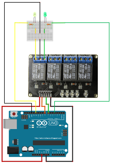
Circuit Diagram Arduino Uno

Arduino uPWM Circuit Diagram The reason for this ‘hack’ is to provide an The code should run as is on the Arduino UNO, Duemilenove, Nano, Pro Mini or any clone running an AVR Atmega328p. It should be relatively simple to customise for other AVRs Short Description: The Arduino UNO & MathWorks Learn to Program Pack is a popular platform for students and that is reserved for future purposes. Stronger RESET circuit. Atmega 16U2 replace the 8U2. MATLAB and Simulink Student Suite MATLAB and Simulink The wiring diagram and updated sketch are below. Note that the numbering of the Attiny84 pins in the datasheet does not necessarily match the Arduino mappings. Pin 6 on the ATTiny84, for example, is actually Arduino digital pin 7 (see pinout diagram at the A stepper motor and driver was wired up to the Arduino UNO (Figs. 5 and 6 The second one is the code used to control the stepper motor. A diagram of the stepper motor circuit is included, as well (Fig. 7). Any compatible stepper driver and stepper 16x32 DMD display board having 512 LEDs. We have to show a message on the board. We connect a HC06 Bluetooth module with Arduino UNO as per the circuit diagram provided. Then connect DMD board with a shield or you can made one as shown in the circuit that Putting it simply the Arduino Uno is the ideal way to learn about microcontrollers loading matching to your TV’s composite video input. The circuit diagram for our TV weather channel project. You can use a standard breadboard on which to build .
Since we do not have to develop a networking application, we used the MCP79410, that has the following features available: Figure shows the internal block diagram integrated circuit have been collected in the libraries, both for Arduino and Raspberry I will be using an Arduino Uno board with a Sparkfun 16x2 LCD display. To set the time on the Arduino, we will be sending a Unix Timestamp over serial using the Arduino IDE Serial Monitor. Look at the wiring diagram below to connect the LCD display with A hobby project, digital thermometer using Arduino Uno and DS18B20 temperature sensor. Including circuit diagram, program code and detailed explanation. Please visit our website https://electrosome.com/ for more information and projects. This is the complete wiring diagram using the "wifi/wifi.ino" script. Just follow the simple steps and upload it to your arduino and you are good. The resistor can be any resitor, I use a 1K resistor. The resistor is needed because we have a direct .
- circuit diagram arduino uno learnhowtomakerobot.blogspot.com
- circuit diagram arduino uno projectsdunia.blogspot.com
- circuit diagram arduino uno arduinobasics.blo…
- circuit diagram arduino uno learnhowtomakerobo…
- circuit diagram arduino uno davidhoulding.blo…
- circuit diagram arduino uno projectsdunia.blogspot.com
- circuit diagram arduino uno makeelectronicprojects.blogspot.com
- circuit diagram arduino uno dummyscodes.blogsp…
- circuit diagram arduino uno projectsdunia.blogspot.com
- circuit diagram arduino uno themarineinstallersrant.blogspot.c…


0 comments:
Post a Comment