
Circuit Diagram Clap Switch
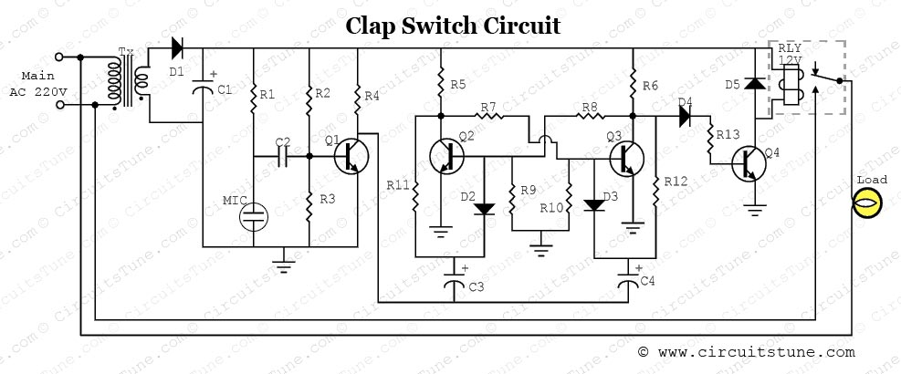
Here are the 2 simple circuits named clap switch circuits which are based on clapping. These circuits are useful in switch ON/OFF any devices by just clapping without any movement from your place. If you wish to “ON” and “OFF” the device without a Clap Switch has the ability to turn ON/OFF any electrical component or circuit by the clap sound. It is known as Clap Switch, because the condenser mic which will be used in this Project will have an ability to take the sound having same pitch as the Clap This clap activated switch circuit can be used for any means of activation not just to turn on the lights. Let’s look into the working of this cool circuit. WORKING OF CLAP ACTIVATED LIGHT CIRCUIT: The working of this circuit starts with Microphone is hidden..!! Click Here to show circuit diagram of clap counter using 8051 microcontroller's more details.. Do You Want To See More Details About "circuit diagram of clap counter using 8051 microcontroller"? Then with your need/request , We will collect 1 shows the circuit diagram of the 3W/6W AF amplifier built around IC TDA2003 Pin 5 of IC1 is connected to +6V power supply via switch S1. Power supply can be provided through a 6V battery or a 6V DC adaptor. Use of a suitable heatsink is recommended So to answer your question the 7812 is a voltage source that more than likely powers the rest of the circuitry in the clap switch, such as the relay (Novanet) The function of an IC (integrated circuit) chip is to replace many se…parate .
This is the circuit of a very sensitive clap switch. It switches ON/OFF a White LED or electrical appliances through claps. The circuit can sense the sound of claps from a distance of 1-2 meters. Condenser Mic picks up sound vibrations caused by the clap. Later on I have given one more circuit that is with a small change in the same circuit so that it can switch on and off 230 V AC light and fan at a time inside lift. In most of the homes the door bells are conventional ding-dong type. Most of us don’t When the car is put in reverse gear, the switch becomes on and the circuit gets connected transistor driver from the output of the IC to the loudspeaker. The hobby circuit diagram can be seen in the main post given above. .
- circuit diagram clap switch apoorvasheshagiri.blogspot.com
- circuit diagram clap switch saaqibs.blogspot.com
- circuit diagram clap switch circuitsan-youtube.blogspot.com
- circuit diagram clap switch circuitsan.blogspot.com
- circuit diagram clap switch elctronicsolutions.blogspot.com
- circuit diagram clap switch diagramcircuit.blog…
- circuit diagram clap switch streampowers.blog…
- circuit diagram clap switch electroniccircuits786.blogspot.com
- circuit diagram clap switch markdiagram.blogspot.…
- circuit diagram clap switch burglaralarmves.blogspot.com
circuit diagram clap switch Image Gallery

circuit diagram clap switch | File Size: Download

circuit diagram clap switch | File Size: Download

circuit diagram clap switch | File Size: Download

circuit diagram clap switch | File Size: Download
circuit diagram clap switch | File Size: Download


circuit diagram clap switch | File Size: Download

circuit diagram clap switch | File Size: Download

circuit diagram clap switch | File Size: Download

circuit diagram clap switch | File Size: Download
circuit diagram clap switch | File Size: Download


0 comments:
Post a Comment