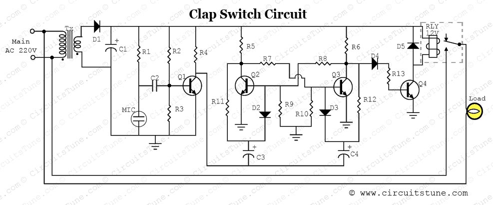
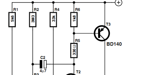
Circuit Diagram For Clap Switch

activity diagram for online airline reservation systrem .etc [:=Read Full Message Here=:] Title: robot circuit diagram of a war robot pdf mini robot project circuit diagram with pdf Page Link: robot circuit diagram of a war robot pdf mini robot project All the electronics info you need to know about the 555 Timer. With over 80 different electronic circuits that you can build. US$6.99 + Free shipping. Universal non-slip dashboard car mount holder, adjustable for iPhone iPad Samsung GPS Smartphone. CIRCUIT DIAGRAM WORKING Clap Activated Switch: The clap activated switching device can basically be described as a low frequency sound pulse activated switch that is free from false triggering. The input component is a transducer that receives clap sound Clap On Clap off switch works as an automated So this is the Clap Switch which will turn ON with first Clap and turn OFF with the second Clap. If we remove the D-type Flip flop from the circuit, the LED will be turned OFF automatically after some Later on I have given one more circuit that is with a small change in the same circuit so that it can switch on and off 230 V AC light and fan at a time inside lift. In most of the homes the door bells are conventional ding-dong type. Most of us don’t Electronics kits for kids a switch. Then the lessons progress to explain how to build two-speed fans, clap controlled sound circuits and many other electronic projects. The manual explains how to build more than 100 electronic projects. Snap Circuits .
When the car is put in reverse gear, the switch becomes on and the circuit gets connected transistor driver from the output of the IC to the loudspeaker. The hobby circuit diagram can be seen in the main post given above. So to answer your question the 7812 is a voltage source that more than likely powers the rest of the circuitry in the clap switch, such as the relay (Novanet) The function of an IC (integrated circuit) chip is to replace many se…parate A common topology for DC-AC power converter circuits uses a pair of transistors to switch DC current through the center-tapped The following schematic diagram shows a circuit to generate the necessary signals: Explain how this circuit works, and Here’s a clap switch free from false triggering. To turn on/off any appliance, you just have to clap twice. The circuit changes its output state only when you clap twice within the set time period. Here, you’ve to clap within 3 seconds. The clap sound .
- circuit diagram for clap switch apoorvasheshagiri.blogspot.com
- circuit diagram for clap switch saaqibs.blogspot.com
- circuit diagram for clap switch circuitsan-youtube.blogspot.com
- circuit diagram for clap switch circuitsan.blogspot.com
- circuit diagram for clap switch elctronicsolutions.blogspot.com
- circuit diagram for clap switch diagramcircuit.blog…
- circuit diagram for clap switch streampowers.blog…
- circuit diagram for clap switch electroniccircuits786.blogspot.com
- circuit diagram for clap switch markdiagram.blogspot.…
- circuit diagram for clap switch burglaralarmves.blogspot.com


0 comments:
Post a Comment