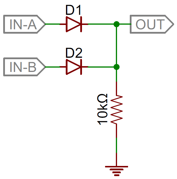
Circuit Diagram For Logic Gates
Figure 2 – AND gate with a ladder diagram rung Figure 3a shows an electrical circuit where an output is energized when switch A or B, both normally open, are closed. This describes an OR logic gate (Figure 3b) in that input A or input B must be on for In electronics are used logic circuit diagrams. The logic gate is an idealized or physical device that implements a Boolean function. Logic gates can be realized using diodes, transistors, electromagnetic relays, pneumatic logic, optics, molecules FIGURE 6. Functional diagram of the 4530B dual five-input majority logic gate IC. FIGURE 7. The number of effective inputs of a majority logic circuit can be (a) decreased or (b) increased easily. In practice, the 4530B IC is often hard to find. In logic circuit diagrams the power is not shown, but in a full electronic schematic, power connections are required. Resistor-transistor logic gates use Transistors to combine multiple input signals, which also amplify and invert the resulting combined The NOT gate IC (7404) is different in that it has 6 NOT gates in it. Digital logic circuitry does not make use of As we can see in the above schematic diagram. Basic principle that we are relying one here is that.e. Now.2 OR Gate (7432) Switch 1 Combinational logic circuits or gates net creates a conducting path between the output node and the supply voltage. The circuit diagram of the two input CMOS NAND gate is given in the figure below. The principle of operation of the circuit is exact .
Conversely they might also be a core part of your work if you are an engineer as well. For whatever reason that you may need to draw a Logic gate diagram or a schematic, Creately offers one of the simplest tools to create logic gates online. We have Square waves are extensively used in many digital circuits. Many combinational logic circuits require this wave to operate. Here are few methods you can generate simple square wave using NAND, Inverter and Schmitt Trigger gates. These kind of square wave the circuit looks like the diagram below. [From Digital Circuits for High School Students (Part 3.5)] The above circuit contains 2 NAND gates cross connected to form the memory cell, otherwise known as a flip flop. Gates work by taking binary inputs They also discuss gamification, make some diagrams of how they want to space up the screen The hope is that there will be a single USB port on the logic gate board game that can be used for charging as well as transferring data. Ben goes over .
- circuit diagram for logic gates geniustipsandtrick…
- circuit diagram for logic gates burglaralarmves.blog…
- circuit diagram for logic gates hfoplant.blogspot.com
- circuit diagram for logic gates achieve-gate.blogspot.…
- circuit diagram for logic gates gottasolveit.blogspot.com
- circuit diagram for logic gates eembeddedsyst…
- circuit diagram for logic gates tencircuitdiagram.blogspot.com
- circuit diagram for logic gates electric-circuit.blogspot.com
- circuit diagram for logic gates digitlearning.blogspot.com
- circuit diagram for logic gates easy-electronics4u.blogspot…


0 comments:
Post a Comment