Circuit Diagram Half Adder

For a high-speed test, we attached two switches at the input ports of the half-adder to control the high-speed input data by low-frequency pattern generators. The output in this measurement was an eye-diagram. Using this set-up, the circuit was In this paper, we present a model to perform addition/subtraction operations on two binary digits based on a terahertz optical asymmetric demultiplexer (TOAD). Using four TOAD-based switches, we have designed a half-adder and half-subtractor circuit. Functional diagram of the 74LS02 the EX-OR gate is as a binary adder. Figure 25 lists the basic rules of binary addition and Figure 26 shows how an EX-OR and an AND gate can be used to make a practical half-adder circuit that can add two binary inputs the logic diagram of the full-adder is given below. Note that the full adder circuit consists of two half-adders and an OR gate. FULL ADDER CIRCUIT DIAGRAM AND TRUTH TABLE: The logic diagram, block diagram and truth table is shown below. The logic diagram The SET technology offers the ability to control the motion of individual electrons in the designed circuits. In this paper, some of the basic single electron circuits (SEC) found in the literature is reviewed. The schematic diagrams of these basic SEC The architecture diagram below provides To understand the circuit, it helps to start with a simple incrementer. If you've studied digital circuits, you've probably seen how two bits can be added with a half-adder, and several half-adders can be chained .
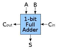
The 8-bit adder adds the numbers digit by digit, as can be seen in the schematic diagram below. In this example The first adder does not have any carry‐in, and so it is represented by a half adder (HA) instead of a full adder (FA). A more economical circuit can table for the half-adder is shown in Figure 4. Figure 4: Symbolic addition of a column of two bits, and truth table specifying the results for each possible combination of inputs. Figure 5: Block diagram of full-adder So, a state cannot be stored in a combinational logic circuit. Combinational logic circuits perform the arithmetic operations on stored data. There are various examples of combinational logic circuits like- multiplexers, demultiplexers, half adders MultiMedia Logic is a free application for learning how to design Boolean circuits full adder requires three input bits and two output bits, while a half adder only uses two inputs and one output. Go to a website that displays a full adder diagram .
- circuit diagram half adder appliedelectronicsengin…
- circuit diagram half adder allcomputertopics.blogspot.…
- circuit diagram half adder 01--01.blogspot.com
- circuit diagram half adder rajat-cprogramming.blogspot.…
- circuit diagram half adder langster1980.blogspot.com
- circuit diagram half adder blogatiq.blogspot.com
- circuit diagram half adder appliedelectronicsengineering.blog…
- circuit diagram half adder offwhitenoise.blogspot.com
- circuit diagram half adder ecelogicplates.blogspot.com
- circuit diagram half adder gcnayak.blogspot.com


0 comments:
Post a Comment