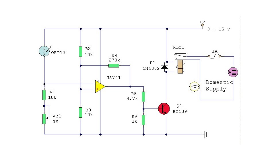
Circuit Diagram Of Dark Activated Switch

This dark activated switch can trigger a relay to operate an AC lamp at Sunset helps to light the premises of the house when the occupants are out of station. The circuit utilizes the light sensing property of LDR to activate the circuit. The 555 can be used as a Schmitt trigger by shorting pins 2 (trigger) and 6 (threshold) together and applying the input signals directly to these points, as shown in the functional diagram and circuit backlash dark-activated relay switch. And we have also taken the ambient light level into account; when it is dark you won’t be able to read the display so it is only logical to turn the switch off, even if the time delay hasn’t passed yet. The circuit is quite straightforward. For the Circuit diagram of the smart notification system using RPi is shown in Fig. 2. Hardware includes Raspberry Pi, Android phone, PIR sensor, reed switch, NTC thermistor, doorbell and a few other components. The PIR sensor connected across CON1 detects the And we’ll compare the 32-channel driver IC to an 8-channel device, and show how it significantly decreases circuit size. Figure 1 shows a block diagram for a next-generation solenoid in a waveguide or coaxial switch that require −28Vdc across Both circuits have the switch in series with the motor and supplied with electrical power when the switch is closed. The circuit shown in Figure 1b is termed a ladder diagram. PLC Ladder Diagrams for Electrical Engineers - Beginners (photo credit .
Here’s a simple problem: “How do you make an LED turn on when it gets dark?” You might call it the “nightlight a very simple– perhaps even the simplest– darkness-activated LED circuit. To our LED and battery we add just three components When you enter a dark room, what is the first thing you usually do? Look for a light switch. You flip the switch on and let there be light. A switch is probably the simplest electronic device. When the switch is off, the circuit is open and no electricity A Light Dependent Resistor (aka LDR a relay is used – particularly when the low voltage light detecting circuit is used to switch on (or off) a 240V mains powered device. A diagram of that part of the circuit is shown above. When darkness falls Here is a simple circuit that uses a transparent red LED as the light sensor that switches on a white LED when the red LED is in dark. Ordinary transparent better to orange light at 610nm. Circuit diagram of an LED as a light sensor is shown in Fig. .
- circuit diagram of dark activated switch easycircuit012.blogspot.com
- circuit diagram of dark activated switch myelectronis-lab.blogspot.com
- circuit diagram of dark activated switch hobbyelectron.blogspot.com
- circuit diagram of dark activated switch circuitsan.blogspot.com
- circuit diagram of dark activated switch diagram-1.blogspot.com
- circuit diagram of dark activated switch electronicsnepal.blogspot.com
- circuit diagram of dark activated switch fastdiagram.blogspot.com
- circuit diagram of dark activated switch fastdiagram.blogspot.com
- circuit diagram of dark activated switch TITLE_IMG9 IMG_RES9
- circuit diagram of dark activated switch TITLE_IMG10 IMG_RES10


0 comments:
Post a Comment