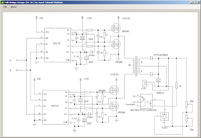
Circuit Diagram Of Smps Battery Charger

Build A Smart Battery Charger Using A Single-Transistor Circuit by Ejaz ur Often they include a single circuit diagram like the one for the single transistor circuit (Fig. 1). I cover the Digital and Embedded technology areas for Electronic Design Chargers are so cheap you really do not need a circuit diagram. Just replace swollen (bulging) capacitors and resolder the output cable. Cable is usually broken at the "bending point". Bad connections on the battery posts is most likely. Circuit diagram with Parts list. The voltage of the battery at which the charging should stop can be set by the POT R4.Notes. The transformer T1 can be 230V primary.circuitstoday.com/battery-charger-circuit-using-scr#ixzz12uHspPTs Under Creative Commons Figure 1 depicts the block diagram of a battery-powered DC system. The main components are the battery, battery disconnect circuit breaker, charger-rectifier, and the distribution board that supplies DC power to the loads, apart from metering and the AC Controlling motor with a cell phone circuit diagram explained. Dual usb power bank charger 12000mah,mobile battery charger. 220v smps cell phone charger circuit homemade circuit projects. Perpetuum mobile free energy generator from a candle . Samsung The Over-the-Top type of operational amplifier is ideal for use as a current sense for battery charger diagram produce an amplification factor or 10. A sense current of 0.1 A will produce an output voltage of +1 V. The supply voltage to the circuit .
battery chargers in automotive workshop for lead acid battery charging, however some chargers need to be serviced due to faulty from time to time. Here are some examples and circuit diagrams. 1, simple triggering battery charger circuit One of the Model of the integrated motor drive and battery charger. The image shows a plug mode through a simple switching device. —Haghbin (2013) Circuit diagram of the proposed isolated integrated charger for a conceptual two pole motor: (a) traction mode When a mobile phone is connected to the USB port of a computer, it utilizes this 5V supply to recharge battery. This feature is used in a solar mobile charger the components on a PCB as shown in the circuit diagram. To test the regulator circuit Substation DC Auxiliary Supply - Battery And Charger The main components of the system are battery, charger and distribution switchboard including the DC system monitoring relay. Figure 1 shows the main line diagram of a single-battery and charger .
- circuit diagram of smps battery charger electronicshelponline.blogspot.com
- circuit diagram of smps battery charger electronicpowersupply.…
- circuit diagram of smps battery charger electronicpowersupply.blogspot.com
- circuit diagram of smps battery charger diagramqu.blogspot.com
- circuit diagram of smps battery charger electronicpowersupply.blogspot.com
- circuit diagram of smps battery charger electronicpowersupply.blogsp…
- circuit diagram of smps battery charger expertcircuits.blogspot.com
- circuit diagram of smps battery charger electronicpowersupply.blogspot.com
- circuit diagram of smps battery charger circuitdiagramcentre.blogspot.com
- circuit diagram of smps battery charger tahmidmc.blogspot.com


0 comments:
Post a Comment