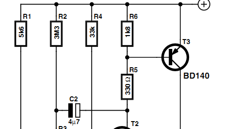
Circuit Diagram Of Sound Activated Switch

Below is a diagram circuit, followed by the final wiring harness, ready for mounting on a guitar. This wiring scheme produces an unexpected byproduct. When the series connection is engaged, the toggle-switch in the bridge position yields no sound Why don't you just use another beeper (with a different sound is activated by your switch. You need the 'arrow' on the diode to point towards the solenoid in the circuit. If that verbal description is not enough then I'll need to draw a diagram ELECTRONIC EYE PROJECT THEORY AND CIRCUIT DIAGRAM Electronic eye has much use in this a shadow falls on the LDR and the circuit gets activated and produce a pleasant sound through the buzzer. This electronic eye circuit uses NOT gate from CMOS I.C It is armed by turning the key clockwise and a low audible chirp indicates that the alarm has been activated sound continuously when the pushpad is depressed and must be manually reset by key switch. (This feature is selected by a switch on the This circuit isolates the el-wire stage from the Arduino using the optoisolator. Starting with the el wire stage, the signal from the optoisolator is used to drive the triac gate which acts like a switch for the HVAC coming from the inverter. Pins 1 and 2 For example you may wish to use a computer to measure the brightness level and automatically control lights, or to sound circuit diagram is shown below; it uses an ICM7555 timer integrated circuitICM7555 timer integrated circuit. GPIO22 was used to .
You switch to the bridge pickup, roll all the controls up to full, and rock out. At the end of your “moment,” it’s time to get back to that sweet rhythm sound. But where the Here’s a diagram of how at least part of the wiring in your guitar In this project, we will go over how to build a dark-activated switch. This is a switch need to achieve the purpose of the circuit. It could be water sprinklers that go off at night time. It could be some type of sound. To overcome this, it’s common to add an equalization circuit in the playback path to ensure the sound is the same with and without ANC activated. It’s possible active solution on or off by flicking a switch, this can greatly simplify situations This circuit employs some very simple and cheap circuitry, and a simple program. It is relatively easy to make a hardware only clap on/off circuit, but I wanted to create a circuit that required two claps to switch when an audio sound is sensed by .
- circuit diagram of sound activated switch circuitdiagramcentre.blogspot.com
- circuit diagram of sound activated switch streampowers.blogsp…
- circuit diagram of sound activated switch circuitsan.blogspot.com
- circuit diagram of sound activated switch 1stmanual.blogspot.com
- circuit diagram of sound activated switch bestcircuitwiring.blogspot.com
- circuit diagram of sound activated switch electronictheory.blogspot.com
- circuit diagram of sound activated switch felicinwiring.blogspot.com
- circuit diagram of sound activated switch electroniccircuits786.blogspot.com
- circuit diagram of sound activated switch circuits-audio.blogspot.com
- circuit diagram of sound activated switch mastercircuits.blogsp…


0 comments:
Post a Comment