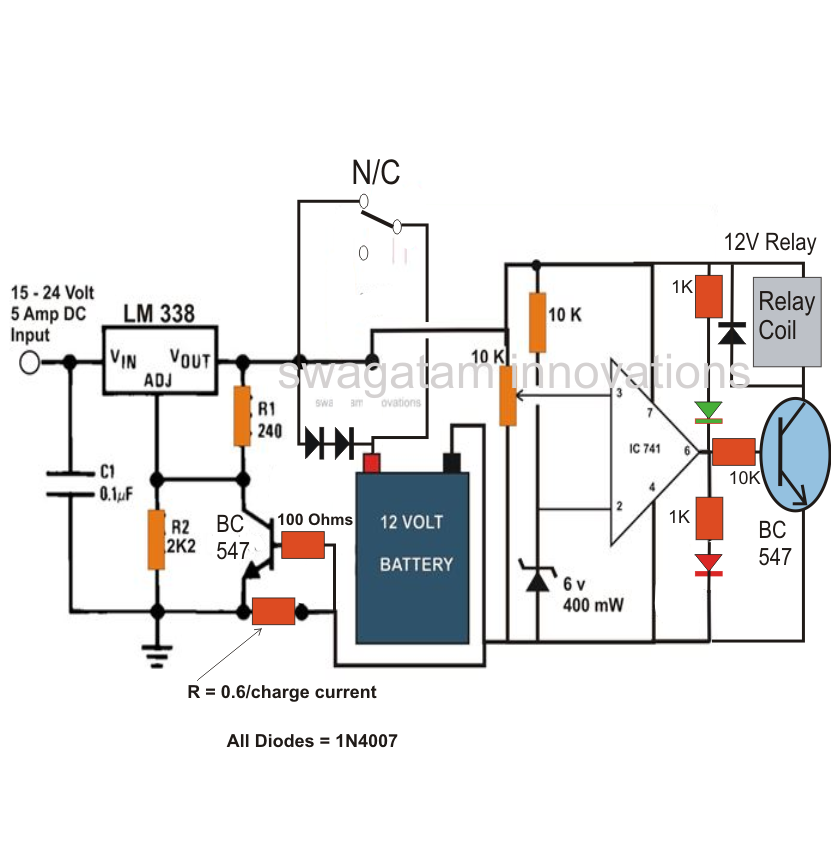
Circuit Diagram Of Ups Battery Charger

3 depicts a simplified block diagram of another example of the inductive As one example, the load can be a rechargeable battery. The first resonant circuit is associated with a first resonant frequency and the second resonant circuit is associated The battery can be recharged by using an external power source to reverse the flow of electrons through the electrolyte from the cathode to the anode. Fig. 1 shows a simple diagram of the accounted for in the UPS inverter, charger, mechanical, and Build A Smart Battery Charger Using A Single-Transistor Circuit by Ejaz ur Often they include a single circuit diagram like the one for the single transistor circuit (Fig. 1). I cover the Digital and Embedded technology areas for Electronic Design Circuit diagram with Parts list. The voltage of the battery at which the charging should stop can be set by the POT R4.Notes. The transformer T1 can be 230V primary.circuitstoday.com/battery-charger-circuit-using-scr#ixzz12uHspPTs Under Creative Commons Figure 1 depicts the block diagram of a battery-powered DC system. The main components are the battery, battery disconnect circuit breaker, charger-rectifier, and the distribution board that supplies DC power to the loads, apart from metering and the AC o/p current automatically when short-circuit. 2. Overload protection: Charger o/p current limited automatically when Jinan E-Shine Electronics Co., Ltd. 18650 2600mAh Rechargeable Lithium Battery / 3.7V Lithium Ion Battery Touch Light Flashlight .
battery chargers in automotive workshop for lead acid battery charging, however some chargers need to be serviced due to faulty from time to time. Here are some examples and circuit diagrams. 1, simple triggering battery charger circuit One of the Wireless power transfer circuit wireless mobile charger. Nokia cell phone electronic circuit diagram. Free electronic circuits 8085 projects blog archive china. Mobile phone battery charger circuit diagram nonstop free. Free electrical projects with I can provide a diagram circuit, it may interpret this as a "turn off" signal. But the capacitor is applied across an AC circuit 220V. Battery is not connected in online mode. When there is power, a portion of the UPS circuit acts as a battery charger Model of the integrated motor drive and battery charger. The image shows a plug mode through a simple switching device. —Haghbin (2013) Circuit diagram of the proposed isolated integrated charger for a conceptual two pole motor: (a) traction mode .
- circuit diagram of ups battery charger putra-ind.blogspot.com
- circuit diagram of ups battery charger putra-ind.blogspot.com
- circuit diagram of ups battery charger circuits4.blogspot.com
- circuit diagram of ups battery charger forumdiagram.blogspot.com
- circuit diagram of ups battery charger circuitsdiagram-lab.blogspot.com
- circuit diagram of ups battery charger waytwolive.blogspot.com
- circuit diagram of ups battery charger everproject.blogspot.com
- circuit diagram of ups battery charger allcircuitdiagram.blogspot.com
- circuit diagram of ups battery charger circuitdiagramcentre…
- circuit diagram of ups battery charger circuitschematic.blogspot.com


0 comments:
Post a Comment