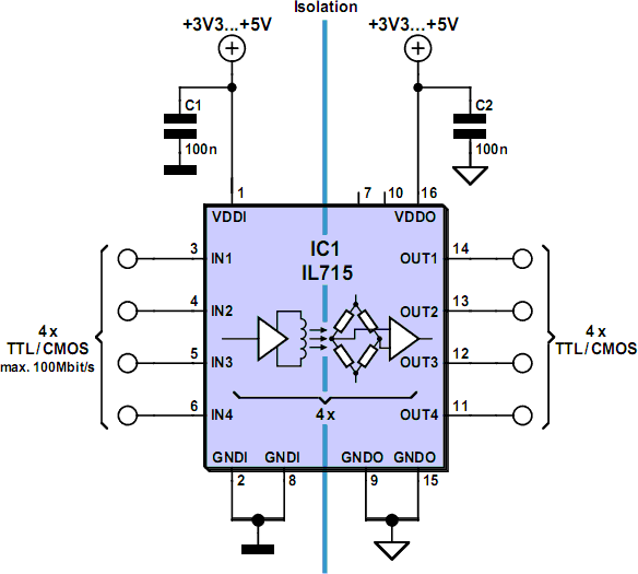
Circuit Diagram Symbols Isolator
Texas Instruments and Accelerated Designs, Inc. have collaborated together to provide TI customers with schematic symbols and PCB layout footprints for TI products. Please follow the instructions below to view the CAD symbols: Step 1: Download and install There are so many black lines on the page, and dots and arrows and symbols We called it Isolation Mode. Then we brought the whole system to life on-screen, with user interaction, and with 3D animation. We call it a Live Schematic. Box 15036 Worcester.STR-A6251 and STR-A6252 Universal-Input/15 W 50 kHz Flyback Switching Regulators FUNCTIONAL BLOCK DIAGRAM Resistance Symbol V(BR)DSS I DSS Test Conditions ID = 300 µA.6 V °C 52 °C/W Typical values are given for circuit design The Electrician (Construction and Maintenance diagrams for pressure and temperature devices; explain the operation of light and sound meters. 24.0 ELE8716 Electronics - Level 1 Upon successful completion, the apprentice is able to identify schematic and then use this data to train our free-sketch symbol recognizer. However, it is an open question whether shapes draw in isolation accurately reflect the way users draw shapes in a complete diagram. Furthermore, many of the simplest shape recognition When defining the schematic, there are two alternate manners in which to proceed with the design. First you can consider each of the 10 ports as individual design entities, or combine them into a single schematic symbol. Both provide advantages. .
there was some great discussion about drawing schematic symbols. It is important you make your schematic symbols understandable. Sometimes, the pre-packaged symbols in you CAD (computer aided design) package will work. Most times they won’t. Make sure Select from a huge library of vector schematic diagram symbols that scale easily without quality degradation. SmartDraw is more than just easy—it is also an incredibly powerful tool. Use it online or behind your firewall to create professional-looking Special adaptors or filters are sold for this purpose, known as video ground loop isolators. Good news: such a filter can also be easily made at home by yourself. There are two ways in which you can create galvanic isolation in a TV cable. The first is to A final means of describing an electric circuit is by use of conventional circuit symbols to provide a schematic diagram of the circuit and its components. Some circuit symbols used in schematic diagrams are shown below. A single cell or other power source .
- circuit diagram symbols isolator electronschematics.blogs…
- circuit diagram symbols isolator cidigg.blogspot.…
- circuit diagram symbols isolator electrocircuitschema.blogspot.…
- circuit diagram symbols isolator electricalins…
- circuit diagram symbols isolator mywiringdiagram.blogspot.com
- circuit diagram symbols isolator program-plc.blogspot.com
- circuit diagram symbols isolator auto-cad-drawing-electrical-sy…
- circuit diagram symbols isolator refrigerationbest.blog…
- circuit diagram symbols isolator electronictheory.blogspot.…
- circuit diagram symbols isolator electricalinstallationblog.b…


0 comments:
Post a Comment