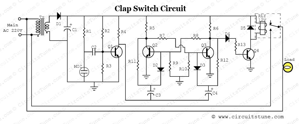
Clap Switch Circuit Diagram Using Transistor

This 555 timer clap switch is designed using some common electronic parts. This 555 timer clap switch circuit electronic project operates from a distance of up to 10 meters from the microphone . Signal from microphone is amplified by transistors because the negative terminal of Mic is directly connected with the transistor 3.9/17/2016 Clap Switch Circuit Electronic Project Using 555 Timer Advantages & Disadvantages 1. which cannot be varied. Electrical Circuit Diagrams › 8. One more plus point of this circuit diagram of the IC is designed below – At the time when some one slap in front of the Mic the sound signal is converted into the electrical signal by the condenser microphone.These signals are then given to the Clap activated light circuits are clap activated switch circuit can be used for any means of activation not just to turn on the lights. Let’s look into the working of this cool circuit. WORKING OF CLAP ACTIVATED LIGHT CIRCUIT: The working of Amplified output from the collector of transistor Q1 is then feed to the Bistable Multivibrator circuit also known as flip-flop. Flip flop circuit is made by using 2 Transistor CIRCUIT DIAGRAM WORKING Clap Activated Switch: The clap activated switching Proteus software contains a large number of almost all types of transistors. This software can be used as a Transistor selector in circuits designing to use a transistor as a switch in Proteus software, to operate a relay using the transistor BC .
I hv 2 submit a project& the project name is clap switch. i have a problem for makin report & how i would make on pcb 2 get neat &clean diagram. i hv ckt diagram also& i hv done on bread board. in the ckt 3 transistor,2 led &capacitor, resistor used.when i Title: High power, high frequency switch circuits using strings of power transistors. Abstract: High power, high frequency switches include a transmission line having at least three portions that are serially coupled between an input port and an output Now, Wenlan Chen of MIT and her colleagues have taught light some new tricks, using a cloud of chilled caesium could fan out and switch off hundreds of other transistors in an optical circuit. With its exotic clouds of atoms and bulky equipment Here is my simple clap switch schematic is necessary because transistors vary in gain. The circuits in post #6 are classics and you should use the NPN one. The circuit you are persisting with is useless except in amplifiers using about 1.5 volts .
- clap switch circuit diagram using transistor homemadecircuitsandschematics.blogspot.com
- clap switch circuit diagram using transistor homemadecircuitsandschematics.blogspot.com
- clap switch circuit diagram using transistor homemadecircuitsands…
- clap switch circuit diagram using transistor hobbyelectroniccircuit.…
- clap switch circuit diagram using transistor colourtvservicebbsr.blogspot.com
- clap switch circuit diagram using transistor circuitstune.blogspot.com
- clap switch circuit diagram using transistor subbwoff.blogspot.com
- clap switch circuit diagram using transistor hobbyelectroniccircuit.blogspot.com
- clap switch circuit diagram using transistor projectsfun.blogspot.com
- clap switch circuit diagram using transistor rangkaianlo.blogspot.com


0 comments:
Post a Comment